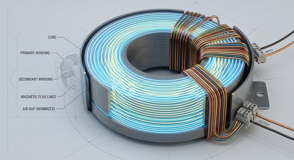
Toroidal transformers reduce noise through three key design features. Their donut-shaped core creates a closed magnetic path. Their windings are symmetrical. They have no air gaps. These traits work together to suppress both acoustic hum and electromagnetic interference.
A Low Noise Toroidal Transformer serves noise-sensitive applications. Audio amplifiers and DACs rely on this electrical transformer for clean power delivery. You will find these devices in recording studios and high-end listening rooms.
This article explains the working principle behind this noise-reduction advantage. You will learn how core construction and winding symmetry keep a toroidal transformer quiet. The design details matter for your next project.
Key Takeaways
A donut-shaped core keeps magnetic flux inside the transformer. This stops stray fields from causing interference.
Symmetrical windings cancel opposing magnetic fields. This reduces electromagnetic noise without extra shielding.
A continuous core without air gaps stops vibration. This makes toroidal transformers up to 8 times quieter than traditional types.
These design features deliver clean power for audio and medical equipment. You get quiet, efficient performance in a small size.
How Toroidal Transformers Reduce Noise
The Toroidal Transformer Working Principle
The working principle of a toroidal transformer starts with electromagnetic induction. An alternating current flows through the primary coil and generates a magnetic field inside the core. This changing magnetic field then induces a voltage in the secondary coil. This is the same working principle you find in any electrical transformer.
The toroidal shape changes how this process unfolds. A donut-shaped core creates a closed loop for magnetic flux. The flux travels in a continuous circle through the core material. This design keeps almost all magnetic flux inside the windings. Stray flux that escapes into surrounding space drops to roughly one-tenth of what EI transformers produce. You get efficient flux circulation with minimal leakage.
The operating principles here differ from traditional laminated designs. A solenoid or EI core lets flux leak through gaps and edges. A toroidal core contains the field within its circular path. This self-shielding behavior means you often need no extra shielding. The compact footprint also saves space on your circuit board.
Toroidal transformers are known for their high efficiency, typically ranging from 95% to 99%. This high efficiency is due to their near-ideal design, which effectively contains the magnetic flux within the windings, eliminating leakage flux.
Symmetry and Field Cancellation
Symmetry plays a central role in noise reduction. The windings on a toroidal transformer distribute evenly around the circular core. This arrangement creates a balanced electromagnetic structure. The operating principles of field cancellation depend on this symmetry.
Consider how current flows through the windings. Radial current segments at equal distances from the axis point in opposite directions. These opposing currents cancel each other out. Axial current on the outside of the toroid flows downward. Axial current on the inside flows upward. Each outer segment matches an equal but oppositely directed inner segment. The net effect on the external magnetic field cancels completely.
This cancellation produces a remarkable result. The magnetic B-field outside the windings drops to zero. Ampere's circuital law confirms this outcome. No current is enclosed by any flux circle outside the winding. The field stays confined within the core. You get total internal confinement of the magnetic field.
The working principle behind this effect relies on axial symmetry. Conductors and magnetic material arrange symmetrically around the axis. No circumferential current exists. Magnetic flux lines form circles of constant intensity centered on the axis. Only flux circles inside the toroidal winding enclose any current. This is why external magnetic fields cancel so effectively.
Common-mode noise suppression also benefits from this design. Toroidal cores maximize magnetic coupling for common-mode signals. They minimize effects on differential signals. This improves noise control across target frequency ranges. The operating principles of symmetry and cancellation work together. They reduce external interference without bulky shielding.
For your noise-sensitive application, this means cleaner power delivery. The Toroidal Transformers design keeps electromagnetic interference contained at its source.
The Toroidal Core Advantage
Tight Core Construction and Windings
The core material in a toroidal transformer comes as ferrite, laminated silicon steel, or another ferromagnetic substance. Manufacturers wind this material into a continuous tape. The process produces a solid, one-piece core with no joints. You get a mechanically rigid structure.
A winding machine places copper wire evenly around the entire core circumference. This uniform coverage uses less total wire than traditional laminated designs. Shorter wire means lower resistance in the windings. Lower resistance directly improves power transfer efficiency. You also achieve higher energy efficiency because less power turns into heat.
The fill factor for toroidal windings typically falls between 20% and 60%. Most applications land in the 35% to 40% range. This high fill factor means the windings fill more of the available window area. The compact arrangement further reduces resistance. A toroidal transformer delivers more usable power per unit of wire than an equivalent EI type.
The Critical Absence of Air Gaps
Traditional EI core transformers have air gaps between their stacked laminations. These gaps interrupt the magnetic path. A toroidal core has no such gaps. The magnetic flux flows in a continuous loop without interruption. This continuous path keeps the magnetic circuit complete.
Audible hum in transformers comes from vibration of windings and core layers. Forces between coil turns and core laminations cause this vibration. In toroidal construction, the core is tightly wound, spot welded, annealed, and sometimes epoxy coated. This construction suppresses vibration effectively.
The absence of air gaps directly contributes to quieter operation. Toroidal transformers achieve this noise reduction because of their smooth flux path. Here is a direct comparison:
Factor
EI Core Transformer
Toroidal Transformer
Noise Result
Core construction
Stacked laminations with air gaps
Continuously wound core without gaps
Toroidal is quieter
Magnetostriction
Higher because of corners and gaps
Lower because of a smooth flux path
Toroidal is quieter
Structural rigidity
Moderate
Very high
Toroidal is quieter
Corners and stress points
Present
None
Toroidal is quieter
Vibration transmitted to enclosure
Higher
Lower
Toroidal is quieter
Overall audible noise
Higher hum
Up to 8 times quieter
Toroidal is quieter
The consistent construction and lack of air gaps reduce magnetic flux spreading. This reduction in fringing also minimizes noise. A Low Frequency Toroidal Transformer uses this design for quiet operation in sensitive industrial environments.
For your application, these features matter. The tight core and gapless magnetic path work together. You get a transformer that runs quietly and with high efficiency. This also means you save on operating costs over the equipment lifetime.
Noise Reduction Advantages
Reducing Acoustic Noise and Vibration
Magnetostriction is the physical vibration that causes acoustic hum in any electrical transformer. As the core expands and contracts with each AC cycle, it produces a faint buzz you can hear in quiet rooms. Tight core construction dampens this effect. A toroidal core is wound continuously, then spot welded, annealed, and often epoxy coated. This rigid structure resists the dimensional changes that magnetostriction tries to force on it. The result is a transformer that runs up to 8 times quieter than an equivalent EI type.
You also benefit from the absence of air gaps. Gaps between stacked laminations act as stress points where vibration concentrates. A gapless core spreads mechanical stress evenly around the ring. The windings sit tightly against the core, so they cannot rattle independently. For audio gear, this means no audible hum bleeding into your signal path.
Minimizing Electromagnetic Interference
The closed magnetic path keeps stray flux away from surrounding circuits. Field lines stay confined inside the core instead of radiating outward. This containment sharply reduces magnetic leakage. Nearby traces and components therefore pick up far less induced noise. A toroidal transformer naturally shields adjacent circuits and lowers the need for extra EMI shielding.
Compare this behavior with boxed designs. E-I or C-core transformers have gaps at the ends of their cores. Magnetic field spills out at these gaps. Engineers must add bulky laminations or external shields to control that leakage. A toroidal core has no air gaps, so nearly all magnetizing energy remains inside the core. This is why toroidal units minimize external magnetic field radiation and reduce mutual coupling to adjacent traces.
The numbers back this up. Toroidal transformers emit EMI at roughly 10 percent of the level from traditional laminated transformers. That equals a 90 percent reduction compared to standard EI types. You get low electromagnetic radiation without adding heavy shielding cans.
An electrostatic shield pushes performance further. A typical shield gives about 60 dB of common mode noise attenuation across the 100 Hz to 1 MHz range.
A typical electrostatic shield gives about 60 dB of common mode noise attenuation over the frequency range of 100 Hz to 1 MHz.
These traits make toroidal transformers ideal for audio equipment. Preamplifiers, DACs, and power amplifiers all need clean rails. Any hum coupled onto a signal trace becomes audible at the speakers. A low noise toroidal design keeps that interference at the source. The same logic applies to measurement gear and medical instruments, where a stray field can corrupt a reading. When you need quiet power, the toroidal transformer delivers it through geometry and construction rather than brute-force shielding.
Sensitive Applications
Clean Power for Audio and Medical Equipment
Audio gear demands a power supply with minimal noise. Preamplifiers, DACs, and power amplifiers all need clean voltage rails. Any hum or ripple that leaks into the signal path becomes audible through the speakers. A standard laminated transformer often introduces this noise through stray magnetic fields and core vibration. A toroidal transformer eliminates both problems with its closed magnetic path and rigid construction. You get a power source that does not corrupt the audio signal. Recording studios and high-end listening rooms consistently choose this design for that reason.
Medical equipment places even stricter requirements on power quality. Devices such as MRI machines and ECG monitors rely on a stable low-noise supply to produce accurate results. Power-line noise or electromagnetic interference can distort measurements and affect patient safety. A toroidal unit meets this challenge by suppressing electrical noise and protecting against AC transients. The key advantages include lower leakage current, reduced electromagnetic interference, smaller size, and quieter operation. These features help manufacturers comply with the following safety standards:
Standard
Edition
UL 60601-1
2nd Edition
ANSI/AAMI ES60601-1
3rd Edition
IEC 60601-1
3rd Edition
ISO 9001:2015
Manufacturing standard
Toroidal transformers provide low acoustic noise by suppressing electrical noise and protecting against AC transients, delivering clean and stable power that is critical for precision equipment such as MRI machines and ECG monitors.
The low audible noise of this design also contributes to a quieter environment in patient rooms and clinical settings. You benefit from both electrical and acoustic silence.
The Role of a Low Frequency Toroidal Transformer
A low frequency transformer serves applications that operate at 50 or 60 Hz. These include industrial automation, power distribution, and renewable energy systems. The toroidal shape allows these units to achieve an efficiency of 90% to 95% at line frequencies. Standard laminated transformers rarely exceed 90% efficiency. The difference means you waste less energy as heat and save on operating costs over the equipment lifetime.
The compact size and low weight of a toroidal transformer also matter in tight enclosures. You can fit more power into a smaller footprint without sacrificing noise performance. The gapless core and symmetrical windings keep electromagnetic interference low even in dense circuit layouts. For sensitive industrial applications where reliability matters, this design provides clean efficient power without adding hum or heat to the environment.
Three design features explain why toroidal transformers reduce noise so well. The closed magnetic path keeps flux inside the core. Tight construction dampens vibration and acoustic hum. Symmetrical windings cancel opposing fields and stop external interference.
These features work as a system. The gapless core removes stress points. The rigid build resists magnetostriction. The balanced windings contain stray flux. Together they cut both audible hum and electromagnetic noise at the source.
You get cleaner power with less shielding and a smaller footprint. For any application where noise is critical, these design advantages make Toroidal Transformers the superior choice. A toroidal transformer simply delivers quieter, more efficient performance.
FAQ
Why do toroidal transformers produce less hum than EI types?
The core has no air gaps. A continuous magnetic path stops the vibration that creates audible hum. Tight construction holds the windings in place. You get a unit that runs up to 8 times quieter than a standard laminated design.
Can I mount a toroidal transformer near sensitive audio circuits?
Yes. The closed magnetic path keeps stray flux inside the core. External fields cancel through winding symmetry. This design emits far less electromagnetic interference than an EI type. You often need no extra shielding for preamplifiers or DACs.
Does core material affect noise performance?
Yes. Ferrite, laminated silicon steel, and other ferromagnetic materials all work. The continuous winding process matters more than the material choice. A gapless core and even winding coverage deliver the noise reduction you want.
What causes acoustic noise in a transformer?
Magnetostriction makes the core expand and contract with each AC cycle. This movement produces a faint buzz. Air gaps and loose laminations amplify the effect. A rigid gapless core resists these dimensional changes and stays quiet.
Are toroidal units suitable for medical equipment?
Yes. Medical devices need stable low-noise power for accurate readings. These transformers suppress electrical noise and protect against AC transients. Their low leakage current and compact size suit MRI machines, ECG monitors, and other precision instruments.
Sourcing electrical infrastructure from overseas presents a tremendous opportunity to reduce capital expenditure, but it also introduces complex supply chain variables. For engineering procurement companies (EPCs) and facility managers, receiving substandard equipment or facing unexpected shipping delays can result in catastrophic project overruns. Mitigating these risks requires a strategic approach to vendor vetting, technical verification, and logistics planning. In this comprehensive guide, we will outline the critical steps global buyers must take to securely and successfully source the right industrial power transformer while minimizing cross-border procurement risks.
1. Verify Manufacturing Capabilities and Grid Compliance
The first line of defense against procurement risk is rigorous supplier qualification. A trading company might offer lower prices, but partnering directly with a reliable transformer manufacturer guarantees direct control over the production process, engineering modifications, and raw material quality. Always request documentation of their ISO 9001 Quality Management System and verify that their production lines are equipped to handle your specific voltage classes and capacity requirements.
Furthermore, electrical grid standards vary drastically across the globe. A unit designed for the European market (IEC standards) may not inherently comply with North American regulations (IEEE/ANSI or UL/cUL standards). Ensure your chosen supplier has a proven track record of exporting grid-compliant transformer equipment to your specific region and can provide the necessary certification marks to pass your local electrical inspections without costly retrofits.
2. Scrutinize Factory Acceptance Testing (FAT) Protocols
Never accept shipment without comprehensive testing data. A trustworthy factory will conduct rigorous Routine Tests on every single unit, including winding resistance measurements, voltage ratio checks, and dielectric withstand tests (applied voltage and induced voltage). For large-scale projects or newly designed equipment, you should also require Type Tests, such as temperature rise tests and lightning impulse tests, to validate the structural integrity of the core and coils.
To further reduce risk, modern buyers are increasingly utilizing remote Factory Acceptance Testing (FAT). Through high-definition video conferencing and real-time data sharing, your engineering team can witness the final testing phase of your custom transformer solution from across the world, ensuring all parameters meet the agreed-upon technical specifications before the equipment is ever crated for export.
Quick Checklist: Evaluating a Global Supplier
Use this risk-assessment matrix to evaluate potential overseas manufacturing partners during the initial sourcing phase.
Risk Category
Verification Actions for Procurement Teams
Production Quality Risk
Audit ISO 9001 certificates; Verify raw material supply chains (e.g., sourcing of high-grade silicon steel and pure copper).
Compliance Risk
Confirm testing aligns with local grid standards (IEC, IEEE, CE, UL) and request past export records to your country.
Performance Risk
Demand comprehensive Factory Acceptance Test (FAT) reports and mandate remote video witnessing before final payment.
Logistical Risk
Review international packaging standards (moisture barriers, impact indicators) and clarify INCOTERMS (e.g., CIF, DDP).
3. Secure Export Packaging and Professional Logistics
Heavy electrical equipment is highly susceptible to mechanical shock, vibration, and moisture damage during prolonged ocean freight. A significant portion of procurement risk lies not in the factory, but on the cargo ship. Ensure your supplier uses heavy-duty, fumigated wooden crates equipped with vacuum-sealed moisture barriers and desiccant packs. For high-voltage oil-immersed power transformers, the factory must equip the shipment with shock indicators (Impact Trackers) to monitor handling quality throughout the journey. Clear communication regarding INCOTERMS (such as FOB, CIF, or DDP) is also essential to determine exact liability transfer points and insurance responsibilities.
4. Establish Clear Warranty and After-Sales Support
The relationship with your supplier should not end when the cargo clears customs. True risk mitigation involves securing a comprehensive, long-term warranty backed by responsive technical support. Verify that the manufacturer provides detailed English-language installation manuals, maintenance guides, and prompt online engineering assistance for troubleshooting. A true OEM partner will also guarantee the long-term availability of spare parts (such as seals, cooling fans, and relays) to protect your investment for decades to come.
FAQ
1. What is a Factory Acceptance Test (FAT) and why is it important?
A Factory Acceptance Test (FAT) is a series of rigorous electrical and mechanical inspections performed at the manufacturer's facility prior to shipping. It ensures the equipment operates safely and strictly adheres to your required specifications, virtually eliminating the risk of receiving defective or non-compliant machinery.
2. How can I ensure a foreign supplier meets my local grid standards?
During the quotation phase, explicitly state your required standards (e.g., IEEE, IEC, CE). Request to see valid certification reports from recognized third-party testing laboratories (like SGS or TÜV) and ask for references or case studies of previous shipments they have successfully delivered to your specific country.
3. What happens if the equipment is damaged during ocean freight?
Liability depends entirely on the agreed INCOTERMS and your cargo insurance policy. For high-value heavy equipment, we highly recommend purchasing comprehensive "All-Risk" marine insurance. Additionally, ensuring the factory uses impact indicators on the crates will help you prove liability if the logistics company mishandles the goods.
Looking for a reliable manufacturing partner with global export expertise?
With decades of OEM/ODM experience, our engineering team ensures total compliance, rigorous FAT testing, and secure global logistics for every project. We eliminate the risks of cross-border procurement.
Consult Our Engineering Team
A power transformer is a static device that transfers electrical energy between circuits via electromagnetic induction. Its primary role is voltage regulation. You likely face a central question: How do you navigate the many transformer types to find the right fit for your project? Confusion often arises from choices like core versus shell type, oil versus dry cooling, or step-up versus step-down. This guide demystifies the types of transformers. It provides a practical framework for selection based on your application needs. You will gain concrete clarity on which electric transformer suits your specific scenario. Understanding the distinctions among transformers empowers informed decisions about these critical components.
Key Takeaways
Understand the main transformer types: step-up, step-down, isolation, and autotransformers.
Choose between single-phase and three-phase designs based on your power needs.
Select the right cooling method: dry-type for indoor safety, oil-immersed for outdoor high voltage.
Use instrument transformers (CTs and PTs) for safe measurement and protection.
Match voltage, capacity, and load characteristics to pick the perfect transformer.
Types of Power Transformers by Function
Function determines how a power transformer serves your system. Each design performs a specific role in the electrical network, from generation through transmission to final consumption. Understanding these functional categories helps you match the right equipment to your operational requirements.
Step-Up Transformers for Generation
Step-up transformers operate at power generation facilities. They receive electricity from generators at relatively modest voltages and increase that voltage for efficient long-distance travel. This voltage elevation serves a critical purpose: higher voltages reduce current for the same power transfer, which minimizes resistive losses across transmission lines.
The voltage increase ratio varies substantially across installations. Typical step-up transformer configurations range from input voltages of 6.3kV to 10.5kV stepped up to outputs of 35kV to 110kV, producing ratios between 3.3 and 17.5. Larger utility installations might use inputs of 10kV to 35kV with outputs reaching 110kV to 220kV, yielding ratios from 3.1 to 22. Some very large generation stations employ even higher ratios, approaching 69.5 when stepping from 11kV-25kV up to 115kV-765kV for ultra high-voltage transmission.
You will find these transformers at hydroelectric dams, thermal plants, wind farms, and solar installations. A generator step-up transformer must handle continuous full-load operation with minimal losses. Manufacturers like RISEN ELECTRIC design these units with robust insulation systems to withstand the thermal and electrical stresses of continuous duty. The selection of a step-up transformer directly influences your transmission efficiency and overall plant economics.
Step-Down Transformers for Distribution
Step-down transformers perform the inverse function. They reduce high transmission voltages to levels suitable for industrial, commercial, and residential consumption. These units appear throughout the power distribution network at various points in the delivery chain.
Substation transformers represent the first stage of voltage reduction. They step down transmission voltages to intermediate levels for regional distribution. Distribution transformers then perform the final reduction, bringing voltage to safe utilization levels for end users. Urban and rural networks rely on these units to deliver electricity at usable voltages while managing load fluctuations across the day.
The types of power transformers in this category include pole-mounted units for residential neighborhoods, pad-mounted enclosures for commercial complexes, and vault installations for underground systems. Each configuration addresses specific space constraints and safety requirements. Distribution transformers often incorporate load management features that help utilities balance demand across their networks.
You should note that the types of power transformers extend beyond simple step-up and step-down functions. Isolation transformers provide electrical separation between circuits without changing voltage levels. These units protect sensitive equipment such as computers and medical devices from electrical noise and surges. They break the galvanic path between input and output, preventing ground loops and reducing electromagnetic interference.
The table below summarizes typical voltage transformation ranges for step-up applications:
Input Voltage (kV)
Output Voltage (kV)
Implied Voltage Ratio Range
6.3 - 10.5
35 - 110
3.3 - 17.5
10 - 35
110 - 220
3.1 - 22
Your choice between step-up and step-down configurations depends entirely on your position within the electrical network. Generation facilities require step-up capability for high-voltage transmission. Distribution utilities and end users need step-down transformers for safe power delivery. Understanding these functional distinctions guides your equipment selection and ensures your system operates with optimal efficiency and reliability.
Single-Phase vs. Three-Phase Designs
The number of phases fundamentally changes how a transformer delivers power. Your choice between single-phase and three-phase designs depends on the scale of your load and the nature of your application. Each configuration serves distinct segments of the electrical network.
Single-Phase for Residential Use
Single-phase transformers deliver power through one alternating current waveform. They supply standard household voltage levels for lighting, appliances, and small motors. Utility companies deploy these units extensively in residential neighborhoods, typically mounting them on poles or placing them in pad-mounted enclosures.
Residential transformers commonly range from 25 kVA to 150 kVA. Standard sizes for single-family homes include 25 kVA, 50 kVA, and 75 kVA. Larger units at 100 kVA and 150 kVA serve apartment buildings or high-load residential complexes. A single-phase transformer suits applications where total demand remains modest and consistent.
You will find that single-phase designs cost less upfront than their three-phase counterparts. However, they exhibit higher no-load and load losses during operation. For small residential loads, this efficiency gap remains minor. The economic disadvantage becomes apparent only when you scale up demand significantly.
Three-Phase for Industrial Power
Three-phase transformers deliver power through three alternating current waveforms, offset by 120 degrees. This configuration provides smoother power flow and higher efficiency for the same total kVA. Industrial facilities, commercial complexes, and utility grids rely on three-phase transformer designs for heavy loads.
The minimum three-phase transformer size for industrial equipment typically starts at 112.5 kVA. Manufacturing plants, data centers, and large commercial buildings require this capacity to operate machinery, HVAC systems, and processing equipment. A three-phase transformer handles these demands with lower operating losses per kVA than comparable single-phase units.
The efficiency gap between configurations widens as load increases. For industrial and data center loads, this difference becomes significant. While a three-phase transformer carries a higher upfront cost than a single similar single-phase unit, it often proves cheaper per kVA than using three separate single-phase transformers of the same total rating. This cost advantage, combined with better efficiency and fewer parts, yields lower long-term maintenance and lifecycle costs.
The table below compares key economic aspects:
Aspect
Single-Phase
Three-Phase
Initial Cost
Lower
Higher
Long-term Losses
Higher
Lower
Overall Efficiency
Lower
Higher
Economic Outcome
Less economical long-term
More economical over time
Your step-down transformer selection for power distribution must account for these phase considerations. A step-down transformer serving a residential subdivision will likely use single-phase construction. Industrial step-down applications demand three-phase designs for adequate capacity and efficiency.
Types of Electrical Transformers by Construction
The physical construction determines a unit's performance, cost, and application suitability. Two fundamental categories dominate the industry: core-type and shell-type designs. Each offers distinct advantages for different operating conditions.
Core-Type and Shell-Type
Core-type units arrange windings around a laminated steel core. The core has two vertical limbs and two horizontal yokes forming a rectangular frame. Primary and secondary windings sit on separate limbs, with the low-voltage winding closer to the core and the high-voltage winding over it. This design exposes windings to ambient air, which improves cooling and contributes to better transformer efficiency. You find core-type units in high-voltage and high-power applications. Their simpler structure reduces manufacturing cost, making them ideal for cost-sensitive projects like rural electrification.
Shell-type units surround the windings with core material. The central limb carries total magnetic flux, while two outer limbs each carry half. Both windings occupy the central limb in layered arrangements. This construction provides higher mechanical strength and a more compact structure. However, enclosed windings reduce natural cooling effectiveness. Shell-type units serve low-to-medium power applications, including distribution and current transformers.
Core type transformers are characterized by low cost and excellent heat dissipation, whereas shell type transformers offer higher mechanical strength and a more compact structure, but at a higher cost.
Autotransformers and Isolation Transformers
Beyond core and shell configurations, specialized types of electrical transformers serve distinct functions. An autotransformer uses a single winding serving as both primary and secondary. This design reduces material usage and size. It provides lower impedance, which improves voltage regulation under load. You use an autotransformer for voltage regulation where galvanic isolation between circuits is unnecessary.
An isolation transformer provides complete electrical separation between input and output circuits. It uses two separate windings with no conductive path between them. The higher impedance can cause greater voltage drop under load, but this impedance helps limit fault current. You apply these units in medical equipment, electronic systems, and sensitive industrial controls.
These types of power transformers represent the primary construction categories. Understanding these types of electrical transformers helps you match design characteristics to your operational demands. Your knowledge of these types of transformers forms the foundation for selecting the right equipment. Among the types of electrical transformers, construction differences matter most for your specific application. These types of power transformers cover the main design variants you will encounter.
Cooling Methods: Dry-Type vs. Oil-Immersed
Cooling method determines where you can install a transformer and how it performs under load. Two primary cooling methods dominate the industry: dry-type and oil-immersed designs. Each serves distinct environments and operational requirements. Your choice between them directly impacts safety, maintenance, and overall system reliability.
Dry-Type for Indoor Safety
A dry-type transformer uses air as the cooling medium. It eliminates the fire risk associated with oil-based cooling. This makes it ideal for indoor installations where fire safety is critical. You find these units in hospitals, hotels, high-rise buildings, and commercial complexes. Dry-type transformers comply with key safety standards including IEC 60076 for design and NFPA 70 for electrical safety.
The standard maximum ambient temperature for dry-type units is 40°C. With Class F insulation, the hot spot temperature limit reaches 155°C at 35°C ambient. The hot spot factor ranges from 1.1 to 1.2, lower than the 1.3 factor for oil-immersed designs. This means dry-type transformers can tolerate higher ambient temperatures before reaching their insulation limit. The table below shows the relationship between insulation class and temperature ratings:
Insulation Class
Ambient Temp (°C)
Rise (°C)
Hot-Spot Temp (°C)
Class A
40
55
95
Class B
40
65
105
Class F
40
80
120
Class H
40
100
140
Dry-type units come in three sub-types. Cast resin units carry the F1 fire behavior rating and are self-extinguishing. They offer excellent moisture resistance and suit humid locations such as hotels and hospitals. VPI units provide good fire performance with low smoke generation. They work well in offices and standard electrical rooms. Open ventilated units offer the lowest cost but require clean, climate-controlled environments. These designs maintain good transformer efficiency in indoor conditions.
Oil-Immersed for High-Voltage Outdoor
An oil-immersed transformer uses mineral oil or synthetic fluids for cooling and insulation. The oil absorbs heat from the core and windings and transfers it to the tank surface. This provides superior heat dissipation for high voltage outdoor applications.
You use oil-immersed units in substations and utility installations where high-voltage transmission requires robust cooling. The oil serves double duty as both coolant and electrical insulator. This combination allows these units to handle higher power densities than dry-type designs of similar size. The hot spot factor for oil-immersed designs is 1.3, higher than the 1.1 to 1.2 range for dry-type units. This means internal temperature rise amplifies more in oil-immersed transformers, and you must account for this factor when sizing the equipment for your load conditions.
Both cooling methods offer high-efficiency designs suited to their operating environments. RISEN ELECTRIC manufactures a complete range of cooling solutions for both dry-type and oil-immersed transformers. Their product line includes cast resin units for indoor safety and oil-immersed units for outdoor installations.
Instrument Transformers for Measurement and Protection
Instrument transformers serve a specialized role in power systems. They scale down high currents and voltages to safe, measurable levels for relays, meters, and monitoring equipment. Without these devices, you cannot accurately measure or protect modern electrical networks. They bridge the gap between raw power and sensitive instrumentation.
Current Transformers (CT) for Metering
A current transformer steps down high line currents to a standardized, low value for measurement. You connect the primary winding in series with the conductor carrying the load. The secondary winding then delivers a proportional current, typically 5A, to your metering equipment.
Metering CTs come with primary ratings from 50A up to 6000A. This range translates to transformation ratios from 50/5A (10:1) to 6000/5A (1200:1). Distribution applications commonly use lower ratios. Standard configurations include 50/5A, 75/5A, 100/5A, 150/5A, 200/5A, and 300/5A. Each ratio serves a specific load range. A 100/5A CT, for instance, accurately measures primary currents from about 70A to 90A.
Protection CTs differ from metering units in accuracy requirements. Grid protection relays demand precise performance under fault conditions. The accuracy class defines the composite error and saturation behavior. The table below summarizes common protection classes:
Accuracy Class
Maximum Error
Typical Application
5P10
5% composite error, ALF = 10
Feeder Protection
5P20
5% composite error, ALF = 20
Transformer Protection
10P20
10% composite error, ALF = 20
Generator Protection
The Accuracy Limit Factor (ALF) indicates the multiple of rated current a CT can reproduce before saturation. A 5P10 CT with a 100/5A rating maintains accuracy up to approximately 1000A. You select the class based on your protection scheme. Feeder protection typically uses 5P10, transformer protection uses 5P20, and generator protection uses 10P20.
Potential Transformers (PT) for Monitoring
A potential transformer steps down high voltage to a safe, standardized level for monitoring equipment. You connect the primary winding across the line. The secondary delivers a reduced voltage to your relays, meters, and protective devices.
Common PT secondary voltages include 100V, 120V, and 69.3V. Industrial metering often uses 100V, such as a 10kV/100V PT. Protection and metering applications commonly use 120V. The 69.3V secondary serves specific protection requirements.
Common PT secondaries include 120V and 69.3V, depending on protection and metering requirements.
A step-down transformer converts voltages such as 480V to 120VAC for monitoring equipment. This confirms 120V as a standard secondary voltage. You select the PT ratio based on your primary system voltage and the requirements of your connected devices. These transformers ensure your monitoring equipment operates safely while providing accurate voltage readings for system control.
How to Select the Right Power Transformer
Selecting the right equipment demands a systematic evaluation of your electrical system's requirements. You must examine voltage levels, capacity demands, load characteristics, and installation constraints. Each factor influences the final specification. A structured approach prevents costly missteps and ensures reliable long-term operation.
Key Criteria: Voltage, Capacity, and Load
Your first step involves matching voltage ratings to your source and load requirements. The primary voltage must align with your incoming supply. The secondary voltage must match your utilization equipment. You also need to consider the basic insulation level (BIL) and whether you require tap changer capability for voltage adjustment. Incorrect voltage ratings lead to overheating or insulation failure.
Voltage regulation matters equally. A lower regulation percentage, typically 0.5% to 2% for power transformers, indicates better output stability under varying loads. Sensitive electronic equipment demands tighter regulation for consistent performance.
The table below summarizes the essential selection criteria:
Selection Criterion
Key Considerations
Voltage Rating
Must match primary (source) and secondary (load) system voltages; includes insulation level (BIL) and tap changer range. Incorrect ratings cause overheating or insulation failure.
Voltage Regulation
Lower percentage (0.5%–2% for power transformers) indicates better stability; essential for sensitive loads and power quality.
Capacity (kVA/MVA)
Must cover continuous, peak, and future loads (20–30% margin). Optimal efficiency at 40–70% load; undersizing causes overheating, oversizing reduces efficiency.
Load Characteristics
Motor loads need 6–8× starting current capability; non-linear loads (VFDs, EV chargers) require K-factor or derating; renewable loads need reverse power flow and harmonic tolerance.
Cooling & Standards
Cooling class (ONAN/ONAF) affects overload capability; sizing follows IEC 60076-7 or IEEE C57.91 for thermal limits.
Calculating your required transformer capacity follows a clear procedure:
Determine the total connected load (in kW) of all equipment.
Apply the demand factor to obtain the maximum expected demand: maximum demand = connected load × demand factor.
Calculate the required apparent power using the power factor: kVA = kW / power factor.
Consider the diversity factor to account for differing peak times of equipment, allowing more accurate sizing.
Add a reserve margin (e.g., 10–20%) for future expansion and safety.
For example, a facility with 800 kW maximum demand and a power factor of 0.8 requires 1000 kVA (800 / 0.8 = 1000). This calculation forms the foundation of your power transformer selection process.
Environmental and Regulatory Factors
Your installation site dictates the cooling method. Indoor locations demand dry-type transformers for fire safety. Outdoor substations can accommodate oil-immersed designs with superior heat dissipation. You must also consider ambient temperature, humidity, and altitude. These environmental conditions affect derating and insulation performance.
Regulatory compliance shapes your specification. International standards govern every aspect of transformer design and testing. The table below outlines the key standards:
Standard
Description
Scope
IEC 60076-1
General requirements
Covers design, construction, and testing fundamentals for all power transformers.
IEC 60076-2
Temperature rise and cooling
Defines thermal limits and cooling methods.
IEC 60076-3
Insulation levels and dielectric tests
Specifies insulation coordination and test procedures.
IEC 60076-5
Short-circuit withstand
Tests ability to withstand short-circuit forces.
IEC 60076-7
Loading guide for oil-immersed transformers
Provides safe loading practices.
IEC 60076-10
Determination of sound levels
Sets noise measurement standards.
IEC 60076-14
Design for ester fluid transformers
Specific requirements for liquid-immersed transformers using biodegradable fluids.
IEC 60076-18
Frequency response analysis (FRA)
Measurement of winding deformation.
IEEE C57 series
Power transformer performance and testing
North American equivalent covering design, test codes, and application guidelines.
These standards directly guide the selection of power transformers by defining performance, safety, and testing criteria that ensure international compatibility.
Energy efficiency regulations also affect your choice. The European standards, specifically EN 50588-1 and EU Regulation 548/2014 (as updated by Regulation 2021/340), impose strict limits on both load and no-load losses for power transformers. In the European Union, replacing outdated transformers with Tier 2-compliant models is now a legal obligation for distribution operators. This mandatory shift has resulted in significant reductions in technical losses, CO₂ emissions, and maintenance costs across the EU grid. The EU Ecodesign Regulation establishes two compliance tiers, with Tier 2 becoming mandatory from July 2021. Tier 2 significantly tightens efficiency requirements for both liquid-immersed and dry-type transformers compared to earlier standards.
Your final specification balances technical performance, operational environment, and regulatory obligations. Consulting with experienced manufacturers like RISEN ELECTRIC ensures your electric transformer meets all applicable codes while delivering optimal transformer efficiency for your specific application.
Common Transformer Applications Across Industries
You encounter transformer applications across industries daily, often without noticing them. Each sector demands specific configurations tailored to its operational realities. Understanding these common transformer applications helps you recognize equipment requirements in your own facility.
Utility and Renewable Energy Sectors
Utility grids rely on transformers at every stage of power distribution. Step-up transformers at generation plants raise voltage for transmission. Step-down transformers at substations reduce voltage for safe consumer delivery. These applications across industries form the backbone of modern electrification.
Renewable energy installations present unique transformer applications across industries. Solar farms use step-up transformers to increase inverter output voltage for grid transmission. Wind farms employ similar units to raise collector system voltage for efficient long-distance power transfer. Hydropower plants boost generator voltage to transmission levels with dedicated transformers.
Wind turbine installations demonstrate specialized transformer design. Pad-mounted transformers sit at the turbine base for compact, outdoor-ready service. Nacelle transformers operate inside the housing, requiring vibration resistance and space efficiency. Collector system transformers at substations provide high reliability for long-distance collection. RISEN ELECTRIC manufactures units for each demanding position.
Manufacturing and Commercial Infrastructure
Industrial facilities depend on robust power distribution equipment. A distribution transformer delivers reliable voltage to production lines, HVAC systems, and processing equipment. Commercial complexes use step-down transformers to convert utility voltages to safe levels for lighting and office equipment.
Healthcare facilities demand exceptional electrical safety. An isolation transformer provides galvanic separation between hospital supply and sensitive medical equipment. This configuration shields devices from power surges, prevents earthing failures, and reduces electromagnetic noise through Faraday shields. Clean power enhances reliability of life-support and diagnostic systems.
A medical isolated-power system includes more than a transformer. Its design may require an ungrounded secondary, controlled leakage and capacitance, continuous insulation monitoring, appropriate distribution equipment, alarms, and application-specific testing. The purpose of this arrangement is not to declare the circuit shock-proof. It is to control ground-fault behaviour and continuously indicate deterioration of the system's isolation so that service continuity and electrical safety can be managed in the way required for the medical location.
Modern grids increasingly deploy smart transformer units with monitoring features. These devices report operational data in real time, enabling predictive maintenance and improved reliability. You will find them in urban substations and renewable installations alike.
You now have a clear mental checklist. Classify by function (step-up or step-down), phases, construction, cooling method, and application. Each category narrows your options toward the right power transformer.
Your choice of transformers balances technical specifications, operational environment, and cost. Voltage ratings, capacity, load characteristics, and site conditions all matter. Use these selection criteria as your starting point. Consult engineers or manufacturers for final specification and sizing.
Transformer technology continues evolving. Smart transformers with real-time monitoring and advanced materials improve grid reliability. Your foundational knowledge positions you to make informed decisions as these innovations arrive.
FAQ
What distinguishes a step-up from a step-down transformer?
A step-up transformer increases voltage at generation sites. A step-down transformer reduces voltage at substations. Your choice between step-up and step-down configurations depends on your position in the electrical network.
How do you calculate the correct kVA rating for transformers?
Determine your total connected load in kW. Apply the demand factor. Divide by the power factor. Add a 10–20% reserve margin for future expansion. This calculation ensures your transformer handles peak demand without overheating.
Can dry-type transformers operate outdoors?
Dry-type transformers suit indoor environments where fire safety matters. Outdoor installations typically require oil-immersed designs for superior heat dissipation and weather protection. Always consult local codes before specifying an installation location.
What is the typical lifespan of a power transformer?
A well-maintained power transformer operates reliably for 20 to 30 years. Factors such as load conditions, ambient temperature, maintenance frequency, and insulation quality directly affect longevity. Regular testing extends service life.
You will typically find an Oil Immersed Transformer installed outdoors in substations, power plants, and industrial facilities. This placement stems from critical cooling needs and fire safety considerations. This article examines these specific locations and the technical reasoning behind them. You will learn about cooling efficiency, safety regulations, and space constraints. We will also contrast these units with dry-type transformers. An oil immersed transformer excels in high-voltage applications where heat dissipation matters most. An oil filled transformer offers superior dielectric strength for demanding environments. Understanding these factors helps you select the right equipment for your project. Proper placement ensures operational safety and long service life.
Key Takeaways
Oil immersed transformers sit outdoors in substations, power plants, and industrial sites. This placement helps with cooling and fire safety.
These transformers use oil for cooling and insulation. The oil absorbs heat and prevents electrical failures.
Choose oil immersed transformers for high-voltage and high-capacity needs. They handle large loads efficiently and last 30-40 years.
For indoor use, you need special fire safety measures. Use fire-rated vaults or less-flammable ester oil.
Compare cooling methods like ONAN, ONAF, and OFAF. Pick one that matches your load and site conditions.
Types of Oil Immersed Transformers by Location
Substations and Power Plants
Substations serve as the critical nodes where voltage transformation occurs across the grid. You will find transmission-class oil immersed transformers handling high-voltage step-up and step-down duties, often operating at voltages up to 765 kV with capacities reaching 1000 MVA. These units rely on sophisticated cooling mechanisms to manage the intense heat generated during operation. The cooling methods include ONAN (natural convection), ONAF (forced air), and OFAF (forced oil and air), each providing distinct thermal management capabilities. For instance, a 100 MVA, 220/66 kV transformer designed for ONAN/ONAF operation carries a base rating of 60 MVA under natural convection and boosts to 100 MVA when fans activate during high-load conditions. This flexibility proves essential for grid stability.
Power plants similarly depend on these robust units to connect generation output to transmission networks. A 100 MW wind farm project, for example, utilized a 60 MVA, 220/33 kV substation transformer with OFAF cooling and a conservator-type design. This configuration linked distributed inverters to the national grid while maintaining thermal capacity under variable renewable loads. The cooling efficiency of oil convection supports long duty cycles and thermal balance, which matters greatly for continuous industrial operation.
Fire safety compliance remains a primary concern in substation design. Operators implement fire barriers, mineral oil alternatives such as ester oils, and detection systems to mitigate hazards. Consider a coastal substation exposed to high humidity and salt air: engineers selected a sealed-type transformer with natural ester oil. This choice delivered fire resistance, zero oil leakage, and stable insulation performance, operating for over five years without incident. Thermal overload protection includes RTDs, cooling fans, and overload relays, while moisture contamination control relies on breather maintenance, seal integrity, and periodic oil testing.
The capacity table below illustrates typical configurations:
Capacity (MVA)
Recommended Cooling
Configuration Type
≤2.5 MVA
ONAN
Sealed or conservator-type
2.5–25 MVA
ONAN/ONAF
Conservator-type with fans
25–100 MVA
ONAF/OFAF
Conservator-type with pumps/fans
>100 MVA
OFAF/OFWF
Conservator-type, high-end grid
Industrial and Renewable Energy Sites
Industrial facilities such as factories and processing plants require robust, high-capacity units to power heavy machinery and continuous production lines. These operations typically employ step-down transformers to reduce transmission voltages to usable levels. You will often specify an Oil Immersed Step Down Transformer for these applications, as it delivers reliable voltage transformation while handling substantial thermal loads. The different types of oil immersed transformers serve distinct roles: distribution units manage local networks, while larger transmission units handle bulk power transfer.
Renewable energy farms present unique challenges. Solar installations in tropical regions benefit from sealed oil-filled designs using ester oil, which provides fire safety and requires minimal service access. Wind farms demand transformers that can handle fluctuating output without compromising reliability. Urban substations typically recommend oil-filled transformers with ONAF or OFAF cooling for high capacity and outdoor durability. The various types of oil immersed transformers each offer specific advantages depending on your site conditions, load profile, and environmental constraints. An oil filled transformer proves particularly economical for large-scale installations where cooling efficiency and dielectric strength outweigh indoor placement concerns.
Applications of Oil Immersed Transformers in Key Sectors
Transmission and Distribution Networks
Power transmission and distribution networks rely heavily on oil immersed transformer technology for voltage transformation across the grid. You will find these units at generation stations stepping voltage up for long-distance transmission, then at substations stepping it down for local distribution. The advantages of oil immersed transformers become evident when you examine their thermal performance. Oil circulates through the core and windings, absorbing heat and transferring it to the tank surface for dissipation. This liquid cooling mechanism maintains uniform temperature distribution, preventing the hotspots that plague air-cooled alternatives.
The dielectric strength of oil also sets these units apart. Oil has a much higher dielectric strength than air, making it ideal for insulating purposes. Additionally, oil fills all internal gaps, eliminating air pockets that could cause partial discharge, and impregnates solid insulation materials, enhancing their performance. This combination of superior heat dissipation and insulation capability explains why utilities specify oil-filled units for critical grid infrastructure.
Distribution networks typically employ units ranging from 30 kVA to 2500 kVA, depending on the load profile. These transformers achieve efficiency greater than 99% at rated load for larger kVA ratings. No-load losses remain low, around 0.2–0.3% of rated power, and load losses stay minimal under heavy demand. Standard capacities include 30 kVA, 50 kVA, 63 kVA, 100 kVA, 160 kVA, 200 kVA, 250 kVA, 315 kVA, 400 kVA, 500 kVA, 630 kVA, 800 kVA, 1000 kVA, 1250 kVA, 1600 kVA, 2000 kVA, and 2500 kVA.
High-Capacity Industrial Use
Industrial facilities demand transformers that can handle continuous heavy loads without compromising reliability. You will find an Oil Immersed Step Down Transformer serving as the interface between utility transmission voltages and plant distribution systems. These units reduce 33 kV or 11 kV incoming supply to utilization voltages suitable for machinery and equipment.
The applications of oil immersed transformers in industrial settings extend beyond simple voltage conversion. Steel mills, chemical plants, and mining operations require units that withstand harsh environmental conditions while delivering consistent performance. Outdoor placement becomes essential for safety, as the oil volume presents a fire risk that indoor installations would amplify. You must also consider environmental containment measures. Bund walls contain oil spills within a confined area, while oil collection pits capture leaked oil for safe disposal. Drainage systems manage rainwater and oil runoff, and separation tanks isolate oil from water for environmental protection. Containment capacity must hold the full oil volume plus additional capacity for rainwater or firefighting runoff.
Regulatory compliance shapes installation decisions significantly. Standards such as IEC 60076 and IEEE C57 address transformer design and safety, while IEC 61936 directly governs high-voltage installations. NFPA 850 provides fire protection recommendations for power plants and substations, and NFPA 70 covers electrical installation safety. ISO 14001 requires environmental management systems that impact oil spill prevention protocols. National regulations add another layer of locally enforced environmental and fire safety codes.
Renewable energy sites present unique requirements. Solar plants require remote monitoring systems for oil leaks, while wind farms emphasize environmental protection measures for transformer oil. Hydroelectric facilities focus on water contamination prevention from oil spills. Each application demands careful consideration of site-specific conditions and regulatory obligations.
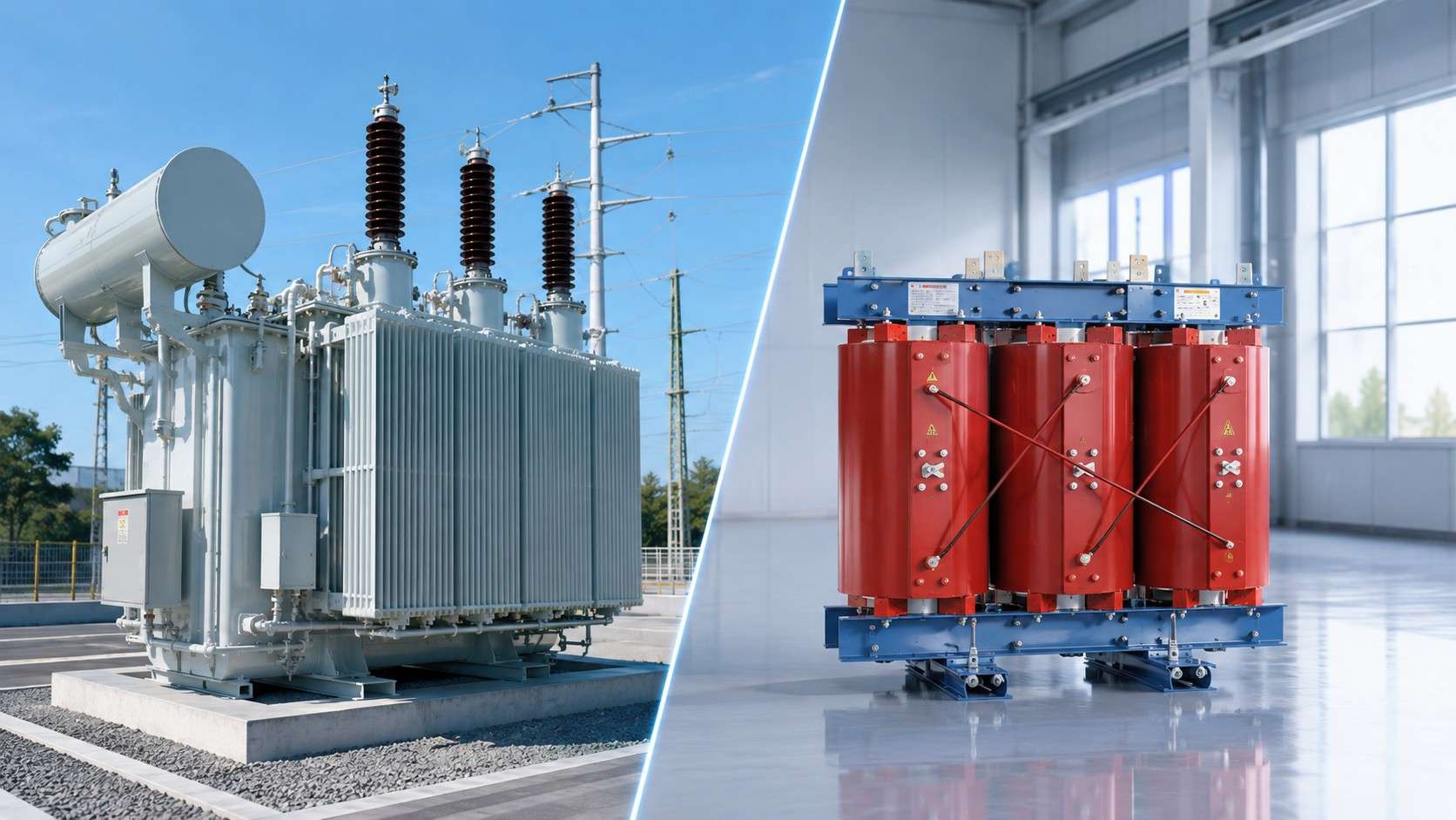
Oil Filled Transformer vs. Dry-Type: Key Differences
Cooling and Safety Trade-offs
When you compare an oil filled transformer against a dry-type unit, the cooling mechanism drives most design decisions. An oil filled transformer uses insulating fluid that circulates through the core and windings, transferring heat to the tank surface where radiators dissipate it. This liquid cooling system provides superior thermal inertia, meaning the unit can absorb short-term overloads without immediate temperature spikes. Dry-type transformers rely on air circulation, which offers far less heat capacity and limits their practical rating for high-voltage applications.
The safety profile differs substantially between these technologies. Mineral oil in an oil filled transformer presents a moderate fire risk because the fluid is combustible. Dry-type units contain no flammable liquid, making them suitable for indoor installation without vault requirements. However, you can mitigate oil-related risks by selecting less-flammable ester fluids or installing fire-rated vaults per NEC 450.23 and 450.26. The environmental trade-off also matters: oil spills require containment and cleanup, while dry-type units pose no leakage risk.
The performance metrics below summarize the key distinctions:
Metric
Oil Filled Transformer
Dry-Type Transformer
Cooling method
Insulating fluid (convection + radiators)
Air (natural or forced)
Efficiency
Higher (lower no-load and load losses)
Lower (higher losses at equivalent kVA)
Overload capability
Excellent due to fluid thermal inertia
Limited by insulation thermal limits
Fire risk
Moderate (mineral oil is combustible)
Very low (no flammable fluid)
Indoor installation
Requires fire-rated vault or less-flammable fluid
Permitted without vault
Cost per kVA
Lower for medium and high voltage
Lower for low voltage
Lifespan
30–40+ years with proper maintenance
25–30 years typical
Selecting the Right Transformer
Your selection criteria should center on voltage class, load profile, and installation environment. For high-voltage transmission and grid interconnection applications exceeding 250 MVA, an oil filled transformer remains the dominant choice. Oil-filled units power over 90% of global electrical distribution systems, a testament to their reliability and cost-effectiveness at scale. You will typically specify an Oil Immersed Step Down Transformer for industrial facilities requiring voltage reduction from 33 kV or 11 kV to utilization levels.
Cooling configuration selection depends on your load pattern. An onan transformer operates with natural convection and suits moderate, steady loads. For variable or high-demand applications, you might choose an ofaf transformer with forced air cooling, or an ofwf transformer with forced water circulation for extreme capacity requirements. Each configuration adds complexity but extends the unit's continuous rating.
Maintenance considerations also influence your decision. An oil filled transformer requires periodic oil testing for dissolved gas analysis, acidity, and moisture content. Dry-type units need only visual inspection. However, the lower initial cost per kVA and longer service life of oil-filled designs make them more economical for large-scale installations. For indoor, low-voltage applications such as data centers, dry-type units offer clear advantages. For outdoor substations and heavy industrial sites, an oil filled transformer delivers superior performance and value.
You now understand why oil immersed transformer installations dominate outdoor substations, industrial yards, and power plants. Cooling efficiency, fire safety compliance, and space constraints drive this placement strategy. An oil filled transformer delivers superior heat dissipation and dielectric strength, making it the economical choice for large-scale, high-voltage applications. For outdoor substations in non-sensitive areas, these units typically offer lower total cost of ownership due to reduced initial capital and better efficiency. Understanding these factors ensures proper transformer selection and placement for your specific operational demands. Consult with engineering experts to evaluate your site conditions, load profiles, and regulatory obligations.
FAQ
What is the typical lifespan of an Oil Immersed Transformer?
An oil immersed transformer typically operates for 30 to 40 years. Regular oil testing and maintenance extend this service life.
Can you install an oil filled transformer indoors?
Yes, but you need a fire-rated vault or less-flammable ester fluid. An oil filled transformer requires proper containment measures for indoor placement.
What cooling method suits industrial applications best?
For variable loads, ONAF cooling provides flexible thermal management. An Oil Immersed Step Down Transformer with forced air handles high-capacity industrial demands.
Which design maximizes heat dissipation in compact spaces?
Oil-immersed transformers with ONAF or OFAF cooling are recommended for urban substations with limited space, as they provide high capacity and reliable outdoor performance.
Selecting the right industrial equipment is not just about matching voltage numbers; it is a critical engineering decision that impacts grid stability, operational costs, and the overall safety of your power distribution system. As modern manufacturing facilities and energy grids grow more complex, the demand for highly efficient and durable power solutions has never been greater. With various capacities, cooling methods, and winding materials available on the market, making the correct choice requires a thorough understanding of your project's specific operational environment. In this comprehensive engineering guide, we will break down the essential steps and core technical parameters to help procurement teams and electrical engineers seamlessly source the perfect industrial power transformer for their next heavy-duty project.
Step 1: Determine Voltage and Load Requirements (kVA)
The fundamental purpose of this equipment is to step up or step down voltage safely with minimal energy loss. You must accurately identify your primary (input) voltage from the utility grid and the secondary (output) voltage required by your machinery. For heavy manufacturing, motor loads, and large-scale commercial facilities, three-phase industrial transformers are the absolute standard due to their stable power delivery, balanced load distribution, and higher electrical efficiency compared to smaller single-phase units.
Equally important is sizing the equipment correctly, which is measured in kilovolt-amperes (kVA). Undersizing leads to dangerous overheating and premature failure, while oversizing wastes capital and increases idle core losses. To determine the right size, sum up the total wattage of all connected equipment, distinguishing between continuous and intermittent loads, and account for motor inrush currents. As a standard engineering rule, always add a 20% to 25% safety margin to your calculated base transformer capacity. This critical buffer accommodates future facility expansions and prevents continuous full-load stress.
Step 2: Evaluate the Operating Environment and Cooling Method
The physical environment—including ambient temperature, humidity, and atmospheric contaminants—where the equipment will be installed dictates both the required enclosure protection and the cooling method. Dry-type cast resin transformers are cooled by natural or forced air ventilation and utilize solid epoxy resin encapsulation for their windings. Because they are virtually fireproof, self-extinguishing, and pose zero risk of toxic fluid leaks, they are the mandated choice for indoor installations, underground transit systems, commercial high-rises, and hospitals.
Conversely, oil-immersed power transformers provide superior thermal heat dissipation through highly refined mineral oil or synthetic dielectric fluids. They are engineered to handle massive voltage capacities and offer incredible longevity in rugged outdoor conditions. They are generally the most cost-effective solution for large-scale utility grids, solar photovoltaic farms, and heavy mining operations. Additionally, you must consider the enclosure rating (such as NEMA or IP) to match the site's environmental hazards.
Step 3: Analyze Energy Efficiency and Total Cost of Ownership (TCO)
Beyond capacity and cooling, evaluating energy efficiency is crucial for minimizing the Total Cost of Ownership. Because these units operate continuously 24/7, even minor inefficiencies can lead to massive electricity costs over a 25-year lifespan. When comparing models, engineers must evaluate both no-load losses (energy consumed by the magnetic core just by being energized) and load losses (heat generated in the windings during operation). Opting for a high-efficiency energy-saving transformer built with advanced amorphous metal cores or high-grade silicon steel can significantly reduce these losses, offering a rapid return on investment while supporting corporate sustainability goals.
Step 4: Smart Monitoring and Grid Integration
As industrial facilities transition toward Industry 4.0, passive power distribution is no longer sufficient. Upgrading to a smart distribution transformer equipped with integrated IoT sensors is rapidly becoming an industry standard. These intelligent systems provide real-time data on critical operational parameters such as oil temperature, pressure levels, dissolved gases, and unexpected load fluctuations. This continuous monitoring enables predictive maintenance, allowing facility managers to identify potential faults before they cause catastrophic downtime, thereby extending the equipment's lifecycle and ensuring uninterrupted production.
Quick Checklist: Key Selection Criteria
Use the following matrix to quickly verify the essential specifications before requesting a customized engineering quote for your project.
Evaluation Factor
Engineering Considerations
Power Rating (kVA)
Calculated total system load + 20% to 25% safety headroom for future expansion.
Cooling Technology
Dry-Type for indoor/fire-safe zones; Oil-Immersed for high-capacity outdoor infrastructure.
Winding Material
Copper for maximum conductivity and strength; Aluminum for budget-friendly utility scale.
Efficiency & Sensors
Evaluate no-load/load losses and consider adding IoT sensors for predictive maintenance.
Enclosure (IP/NEMA)
Match the structural rating strictly to environmental hazards (dust, moisture, corrosive chemicals).
Step 5: Certifications, Testing, and OEM Customization
Choosing the right technical specifications means little if the equipment fails to meet global safety standards. Ensure the equipment complies with rigorous international grid codes by choosing CE, UL, or IEC certified transformers. Partnering with a manufacturer that operates under strict ISO quality management systems guarantees that your equipment undergoes comprehensive Factory Acceptance Testing (FAT), ensuring long-term reliability before it even leaves the production line.
Furthermore, standard off-the-shelf products might not perfectly align with complex industrial setups or specific harmonic distortions. Working directly with a certified OEM/ODM factory allows for deep technical customization—from tailored physical dimensions and specialized K-factor ratings to specific impedance requirements—ensuring a flawless and highly efficient integration into your existing power infrastructure.
FAQ
1. Should I choose Copper or Aluminum windings for my project?
Copper offers superior electrical conductivity, mechanical short-circuit strength, and allows for a more compact core design, making it ideal for space-constrained or extremely high-reliability applications. Aluminum is significantly lighter and more cost-effective, making it a highly reliable and popular choice for large-scale utility projects where weight constraints and overall budget are primary concerns.
2. Why is adding a 20% safety margin to the kVA rating necessary?
Adding an engineered safety margin prevents the unit from operating at 100% capacity continuously, which can cause severe overheating, degrade the insulation, and reduce its operational lifespan. It also safely accommodates motor startup inrush currents and provides essential headroom for adding more machinery to your facility in the future without needing an immediate upgrade.
3. What is the difference between no-load losses and load losses?
No-load losses (core losses) occur continuously as long as the unit is energized, regardless of whether any power is being drawn by the facility. Load losses (copper losses) occur in the windings and vary depending on the actual electrical load being drawn. Evaluating both is essential for calculating the true operational cost of the equipment.
4. Can you customize equipment for extreme environments?
Absolutely. As an experienced industrial manufacturer, we offer extensive OEM/ODM customization services. We can engineer equipment with high IP/NEMA rated enclosures for severe dust, specialized anti-corrosion coatings for offshore or marine environments, and heavy-duty cooling systems designed specifically to operate reliably in extreme ambient temperatures.
A practical procurement guide by Foshan Risen Electric Co., Ltd.
Across West and East Africa, the 33kV sub-transmission level is the backbone of regional power distribution. Utilities and EPC contractors step 33kV down to 11kV at regional substations, then feed distribution networks that supply industrial zones, residential areas, and commercial loads. Getting the specification right at this stage determines whether the substation performs for 25 years — or becomes a maintenance headache after three.
As a transformer sourcing and supply chain company, we receive inquiries for 33/11kV units every week from buyers across Africa and the Middle East. This guide distills what we check in every single inquiry, so you can approach your supplier with a specification that is complete, correct, and priced fairly.
Step 1: Get the capacity right — for 5 years, not today
The most common mistake we see is under sizing. Buyers specify for current peak load, and the substation hits its limit within 2–3 years.
● Calculate the current peak demand(kVA), not the connected load.
● Add 5-year load growth— typically 6–10% annually in fast-growing African distribution networks.
● Consider future feeders: if the substation will serve a new industrial park in 2 years, build that into the rating now.
Standard 33/11kV distribution transformer ratings include 5, 7.5, 10, 12.5, 15 and 20 MVA. Going up one step now costs far less than re-procuring later.
Step 2: Decide the tap changer type early
On-load tap changer (OLTC): regulates voltage while energized. Recommended when the 33kV feeder is long and voltage varies between day and night peaks — a common condition on rural feeders.
Off-load (DETC): adjustable only when de-energized. Acceptable on stable urban feeders where voltage fluctuations are small.
If in doubt, ask your supplier to explain the voltage profile implications for your specific feeder. A good supplier will recommend OLTC for long rural feeders even when it costs more, because a unit that cannot hold voltage is a unit that fails commercially.
Step 3: Confirm ambient temperature and altitude derating
This is the detail that gets skipped, and it shortens transformer life.
IEC 60076 ratings are based on a reference ambient temperature of 40°C (daily average over 24h).
If your site regularly exceeds this — many African sites reach 42–45°C in hot season — the unit must be designed with appropriate temperature rise limits or reinforced cooling.
Altitude above 1,000m also requires derating per IEC 60076-1.
Provide the supplier with the site's ambient temperature profile, not just "hot climate". The correction is engineering, not guesswork.
Step 4: Lock the standards, frequency, and test requirements
Frequency: 50Hz across Africa and the Middle East.
Standard : IEC 60076 is the baseline. Many utilities also require conformity to local grid codes or specific approval processes.
Routine tests you must receive: winding resistance, turns ratio, impedance voltage, dielectric tests, induced over-voltage, and no-load/load loss measurements. Ask for the full test report pack before production starts, not at delivery.
A supplier who cannot show traceable routine test data for previous units is a supplier to be cautious about.
Step 5: Plan cooling, enclosure, and installation
Cooling: ONAN (oil natural, air natural) is standard for most 33/11kV distribution transformers. ONAF adds forced-air cooling for higher peak capacity.
Outdoor installation: the unit is pad-mounted, usually with a corrugated tank design. Confirm the tank finish is suitable for your site's conditions (coastal salt, high UV, heavy rain).
Protection accessories: conservator or hermetically sealed design, Buchholz relay (for larger units), oil temperature indicator, and pressure relief device should be confirmed in the specification.
Step 6: Ask these 5 questions before signing
1. What is the firm lead time, in writing, and what happens if it slips?
2. Can I receive the routine test reports before shipment?
3. What derating assumptions were used for my site's ambient temperature and altitude?
4. What warranty applies, and how are claims handled internationally?
5. What documentation ships with the unit (invoice, packing list, certificate of origin, test reports)?
Global transformer lead times in 2026 are running at 30–50 weeks. A supplier with real factory capacity and a coordinated supply network can make the difference between a project delivered on schedule and a project delayed a year.
How we work with buyers on these projects
Foshan Risen Electric operates as a sourcing and supply chain partner: we qualify and audit specialized transformer factories across China's manufacturing hubs (Jiangsu, Zhejiang, Hebei), match your specification to the right facility, monitor production through a four-stage QC protocol (IQC/IPQC/FQC/OQC), and manage pre-shipment inspection and export documentation.
When you send us your load data and site conditions, our engineering team returns a technical review and a quotation within 24 hours — with the derating assumptions, test plan, and lead time spelled out. No off-the-shelf compromise, no vague "market price" quotes.
Get a technical quotation here!
FAQ
Q1: What is the typical voltage ratio at a regional substation in Africa?
A: The most common sub-transmission level in English-speaking African markets is 33kV, stepped down to 11kV for distribution or 0.415kV for LV supply, per IEC 60076.
Q2: When does a 33/11kV transformer need an on-load tap changer?
A: When the 33kV feeder is long or voltage varies significantly between day and night. On stable urban feeders, off-load tap changers may be acceptable at lower cost.
Q3: What test reports should a buyer request?
A: Full IEC 60076 routine test reports: winding resistance, turns ratio, impedance voltage, dielectric, induced over-voltage, no-load and load loss. Request them before production begins.
Q4: How long does a 33/11kV unit take to deliver in 2026?
A: With a coordinated multi-facility supply network, we quote 8-10 weeks for this class — well under the 30–50 week global average for transformer deliveries this year.
Quick Answer
A dry-type transformer is a completely solid-state power distribution device that utilizes natural or forced air to cool its internal windings, entirely eliminating the need for combustible insulating liquids like oil. Operating on the principle of electromagnetic induction, it steps voltage up or down while providing maximum fire safety, making it the premier choice for indoor substations, commercial high-rises, and demanding industrial environments.
Key Takeaways
Ultimate Fire Safety: Operates entirely without oil, utilizing self-extinguishing cast resin or varnish, eliminating the risk of leaks, fires, and explosions.
Maintenance-Free Operation: Requires no periodic oil testing, filtration, or fluid replacement, drastically reducing long-term lifecycle costs.
Eco-Friendly Design: Contains no toxic chemicals or groundwater pollutants, supporting LEED and BREEAM green building certifications.
Versatile Installation: Can be installed directly at the load center indoors, or outdoors when equipped with specific NEMA-rated weather enclosures.
1. The Core Concept: What Exactly is a Dry-Type Transformer?
In electrical power distribution, transformers are essential for stepping high transmission voltages down to usable levels for facilities and equipment. Traditionally, these massive units were filled with mineral oil to insulate the electrical coils and dissipate heat. However, oil introduces significant fire risks and environmental hazards.
A dry-type transformer revolutionizes this process. Instead of sitting in a tank of liquid, the magnetic core and copper (or aluminum) windings are either encased in a solid epoxy resin (Cast Resin) or vacuum pressure impregnated (VPI) with specialized varnishes. Because they are "dry," these units rely on the ambient air circulating around their coils for cooling. This fundamental design shift means they can be safely installed in highly populated areas, underground transit systems, and sensitive environments like data centers or hospitals.
2. The Mechanics: How Does a Dry-Type Transformer Work?
Despite the difference in cooling mediums, dry-type transformers operate on the exact same fundamental electrical principles as their liquid-filled counterparts: Faraday’s Law of Electromagnetic Induction.
Here is the step-by-step breakdown of the operational process:
Primary Winding Excitation: High-voltage alternating current (AC) from the power grid enters the primary windings of the transformer.
Magnetic Flux Generation: As this current flows through the primary coil, it generates a continuously changing magnetic field (flux) within the highly permeable silicon steel magnetic core.
Electromagnetic Induction: This fluctuating magnetic field travels through the core and intersects with the secondary windings.
Voltage Step-Down (or Step-Up): The magnetic field induces a new AC voltage in the secondary coil. The output voltage is directly proportional to the ratio of the number of turns in the primary coil versus the secondary coil. For example, a common industrial application will step a 13.8kV input down to a 480V output.
3. Thermal Management: How Do They Stay Cool?
Because there is no oil to absorb the intense heat generated by electrical resistance, dry-type transformers rely on advanced airflow engineering.
AN (Air Natural) Cooling: In standard operation, the transformer uses natural convection. As the windings heat up, the surrounding air warms and rises, drawing cooler air in from the bottom of the enclosure.
AF (Air Forced) Cooling: During periods of peak power demand or emergency overloads, intelligent thermal monitoring systems activate integrated cooling fans. This forced airflow dramatically accelerates heat dissipation, allowing the transformer to temporarily operate at capacities up to 33% beyond its base rating.
Dry-Type vs. Oil-Immersed Transformers: A Technical Comparison
When engineers design a new substation, selecting between dry-type and oil-immersed units is a critical decision. Here is a breakdown of how they compare:
Feature
Dry-Type Transformers (Cast Resin)
Oil-Immersed Transformers
Cooling Medium
Ambient Air / Solid Epoxy Resin
Mineral Oil / Natural Esters
Fire Safety
F1 Class (Self-extinguishing)
High risk (Requires firewalls)
Maintenance
Minimal (Visual checks, dusting)
High (Oil testing, leak repairs)
Installation Space
Indoors (Directly at load center)
Outdoors / Remote vaults
Environmental Impact
Zero spill risk, non-toxic
Risk of soil and groundwater pollution
Upfront Cost
Slightly higher
Lower
Long-Term ROI
High (Low operational costs)
Moderate (Ongoing maintenance)
Real Case Application: High-Efficiency Power Distribution in Modern Infrastructure
To understand how these systems perform in the real world, consider the deployment of the SCB13 Series Eco-Efficient Cast Resin Dry-Type Transformer in a recently constructed commercial high-rise complex.
Project Parameters & Equipment Specs:
Capacity: 2500kVA
Voltage Ratio: 11kV stepping down to 0.415V
Standards: Fully compliant with IEC 60076 and CE standards, achieving IE4 ultra-high efficiency benchmarks.
Insulation: Class F/H advanced vacuum resin casting.
The Application Scenario:
The project developers required a high-capacity power solution that could be installed safely in the basement levels of the commercial complex without violating strict urban fire codes. The SCB13 dry-type transformer was selected due to its completely oil-free, flame-retardant structure.
By utilizing imported high-permeability silicon steel sheets, the unit significantly reduced standby power consumption (no-load losses). Furthermore, the advanced vacuum casting process maintained partial discharge (PD) levels at ≤10pC, ensuring long-term dielectric reliability. The unit's ultra-quiet operation (<55dB) meant it could operate continuously without disturbing the office tenants above, while its intelligent thermal monitoring system provided real-time data to the building's central control room, empowering facility managers with a truly maintenance-free, set-and-forget power solution.
Frequently Asked Questions (FAQs)
Q1: What is the average lifespan of a dry-type transformer?
A: When properly specified and installed in a well-ventilated environment, a premium cast resin dry-type transformer is designed to operate reliably for 25 to 30 years or more. Because there is no insulating fluid to degrade over time, the solid insulation maintains its dielectric strength for decades, provided the unit is kept free of extreme dust accumulation and operates within its rated temperature limits.
Q2: Can dry-type transformers be installed outdoors?
A: Yes. While they are the standard choice for indoor installations, dry-type transformers can be safely installed outdoors when equipped with the appropriate protective enclosures. By utilizing a NEMA 3R enclosure (for weather resistance against rain and ice) or a NEMA 4X enclosure (for severe corrosive environments like marine ports or chemical plants), they can deliver robust performance in harsh outdoor climates.
Q3: Are dry-type transformers more expensive to operate than oil-filled ones?
A: While the initial capital expenditure (CAPEX) for a dry-type transformer can be slightly higher than an equivalent oil-immersed unit, the operational expenditure (OPEX) is significantly lower. The total cost of ownership over a 20-year lifecycle heavily favors dry-type units because they eliminate the costs associated with periodic oil sampling, filtration, fluid replacement, and the construction of expensive fire-containment vaults.
Global power grids are experiencing unprecedented structural pressure. A confluence of rapid urban densification, the accelerated adoption of electric vehicles, and the widespread integration of distributed energy resources (DERs) like solar and wind has transformed the traditional model of central power generation. Electrical utilities and industrial enterprises are no longer just delivering electricity; they are managing complex, dynamic energy ecosystems that demand exceptional speed, resilience, and adaptability.
For decades, expanding power capacity meant constructing traditional brick-and-mortar substations. These expansive civil engineering projects required massive land footprints, multi-year permitting processes, extensive site preparation, and month-long on-site assembly of individual components. In today’s fast-moving industrial landscape, where project timelines are measured in weeks rather than years, this legacy approach frequently creates costly bottlenecks.
To overcome these limitations, modern electrical engineering has embraced pre-engineered, factory-assembled modular architectures. Implementing comprehensive Compact Substation Solutions has become a primary strategy for utilities, renewable energy developers, and industrial operators seeking to drastically reduce spatial footprints, lower total cost of ownership, and enhance grid elasticity without compromising safety or performance.
Rethinking Infrastructure: The Shift from Civil Works to Modular Engineering
The core philosophy behind compact power distribution lies in the seamless integration of high-voltage switchgear, step-down or step-up power transformers, and low-voltage distribution panels within a single, fully enclosed housing. By shifting the bulk of construction and testing from the unpredictable outdoor field environment to a controlled factory setting, engineers can eliminate hundreds of hours of site-related risk.
Traditional substations often suffer from construction delays caused by adverse weather, labor shortages, and complex multi-vendor component integration on-site. Modular substations, by contrast, arrive at the location pre-wired, factory-tested, and ready for immediate connection.
Feature / Operational Dimension
Traditional Masonry Substation
Outdoor Compact Substation
Temporary Mobile Substation
Physical Footprint
Extremely large (Requires dedicated land & multi-room buildings)
Highly compact (Occupies a few square meters on a pad)
Ultra-compact (Fits standard ISO container or trailer chassis)
Deployment Timeline
6 to 18 months
2 to 6 weeks
Hours to days (Plug-and-play capability)
Civil Work Requirement
Extensive foundations, walls, cable trenches, and roofing
Minimal (Requires only a leveled concrete pad)
Near zero (Leveled ground or temporary support pads)
Environmental Protection
Dependent on building maintenance & room HVAC systems
Superior (Corrosion-resistant, hermetically sealed enclosures)
Engineered for rugged, high-vibration industrial sites
Relocation Potential
Zero (Fixed permanent structure)
High (Can be unbolted and crane-lifted to new sites)
Maximum (Trailer-mounted or skid-mounted for continuous mobility)
Outdoor Oil Immersed Compact Substations: Engineered for Heavy Loads and Harsh Climates
When power infrastructure must operate outdoors continuously over decades, environmental exposure presents severe risks. Extreme ambient temperatures, salt fog in coastal regions, high humidity, airborne particulate matter, and intense solar radiation can quickly degrade unshielded electrical components.
In these demanding outdoor applications, oil-immersed transformer technology remains the gold standard for thermal management and dielectric strength. Unlike dry-type transformers, which rely on forced air circulation and ambient thermal dissipation, oil-immersed systems submerge the core and active windings in specialized dielectric liquid—typically highly refined mineral oil or biodegradable synthetic esters.
1. Advanced Thermal Convection and Overload Capability Dielectric oil functions simultaneously as a high-performance electrical insulator and a highly effective heat transfer medium. Heat generated within the transformer coils during operation is transferred via natural thermosiphon convection (or forced pump circulation) to external radiator panels or corrugated tank walls. This superior cooling mechanism grants oil-filled transformers a significantly higher thermal time constant, allowing them to handle sudden, severe load spikes—such as peak evening residential demand or heavy industrial motor startups—without incurring insulation damage.
2. Sealed Defense Against Atmospheric Degradation Because the active electrical core is completely encapsulated within a hermetically sealed tank, it remains entirely isolated from external atmospheric contaminants, moisture, and oxygen. This design virtually eliminates the risk of winding oxidation or dielectric breakdown caused by humidity ingress. When selecting an Outdoor Oil Immersed Compact Substation for utility distribution or industrial facilities, operators benefit from heavy-gauge steel enclosures treated with multi-layer anti-corrosion coatings. These pad-mounted units feature tamper-resistant, dead-front construction that ensures complete public safety while blending unobtrusively into commercial or suburban landscapes.
3. Aesthetic Integration and Spatial Efficiency Pad-mounted oil-immersed substations feature a low-profile design, often finished in neutral tones to blend seamlessly with landscaping or industrial architecture. By housing the high-voltage ring main unit (RMU), oil transformer, and low-voltage distribution board in adjoining compartmentalized sections within a single cabinet, these units eliminate the need for overhead line drops and exposed busbars, drastically improving both visual quality and site safety.
Temporary Power Mobile Substations: The Rapid-Deployment Workhorses
While fixed compact substations resolve spatial and environmental challenges for permanent installations, modern industries increasingly encounter scenarios where electrical demand is inherently transient, unpredictable, or geographically shifting. In these dynamic environments, permanent infrastructure is economically impractical and logistically impossible.
Mobile substations represent the apex of fast-response power engineering. By mounting complete high-voltage to medium-voltage distribution systems onto heavy-duty road trailers, multi-axle skids, or standardized ISO shipping containers, electrical engineers have created a mobile power asset capable of rapid deployment anywhere accessible by road or heavy haulers.
1. Mining, Extraction, and Heavy Civil Engineering In open-pit mining, quarrying, and major tunnel construction, the active working face continuously moves as mineral extraction progresses. Massive electric draglines, hydraulic shovels, and mobile crushing plants consume megawatts of power but must relocate frequently. A stationary substation would quickly leave equipment stranded beyond economical cable transmission lengths. Trailer-mounted mobile substations move alongside the mining operation. Fitted with reinforced structural framing, heavy-duty vibration isolators, and quick-connect medium-voltage couplers, these units allow operators to maintain short cable runs, minimize line losses, and relocate entire power distribution nodes in a single shift.
2. Emergency Response and Grid Restoration When severe weather events, natural disasters, or unexpected equipment failures paralyze a primary utility substation, restoring power to critical infrastructure—such as hospitals, water treatment plants, and emergency communications—is a race against time. Rebuilding a damaged conventional substation bay can take weeks or months. Mobile substations serve as immediate grid replacements. Equipped with integrated protection relays, lightning arresters, and pre-wired cable reels, these units can be hauled to the site, grounded, connected to overhead or underground lines, and energized within hours of arrival.
3. Uninterrupted Power During Maintenance and Upgrades As power utilities modernize aging transformer fleets, performing major overhauls or transformer replacements traditionally required extended planned outages for downstream consumers. By connecting a mobile substation in parallel as a temporary bypass, utilities can isolate the primary transformer bay for maintenance while maintaining uninterrupted service to thousands of customers, thereby avoiding substantial regulatory penalties and lost revenue.
Smart Integration: Converting Modular Hardware into Intelligent Grid Assets
The physical compactness and mobility of modern substations are further enhanced by digital intelligence. The convergence of Industrial Internet of Things (IIoT) architecture, smart sensors, and edge computing has transformed these modular enclosures into highly transparent nodes within modern smart grids.
Historically, monitoring remote or temporary substations required physical site visits by maintenance crews. Today, integrated sensor arrays continuously monitor vital parameters:
Thermal Metrics: Real-time top-oil and winding temperature tracking.
Dielectric Health: Moisture-in-oil sensors and online dissolved gas analysis (DGA) to detect early insulation degradation.
Electrical Dynamics: Microprocessor-based protection relays logging voltage fluctuations, harmonic distortion, and load profiles.
Environmental Security: Intrusion detection, internal ambient humidity sensors, and automated fire suppression status.
These data streams are transmitted wirelessly via secure 5G or satellite communication links back to central Supervisory Control and Data Acquisition (SCADA) platforms. Advanced machine learning algorithms analyze these operational metrics in real time, shifting maintenance strategies from reactive troubleshooting to predictive health management. This intelligent oversight ensures that whether a substation is bolted permanently to a city pad or towed across a dusty mining haul road, operator intervention occurs before minor anomalies escalate into catastrophic failures.
Building a Flexible and Resilient Power Infrastructure
The transformation of the global energy landscape requires a fundamental shift in how electrical power is distributed and managed. The rigid, slow-to-deploy civil engineering models of the past are rapidly giving way to flexible, modular, and highly adaptable distribution paradigms.
Fixed outdoor compact units and highly maneuverable mobile stations work in tandem to solve the dual challenges of space constraints and operational volatility. Compact, oil-immersed configurations provide the durable, weather-resistant foundation needed for long-term urban density and heavy industrial expansion. Meanwhile, containerized and trailer-mounted systems offer unmatched operational agility, serving as dynamic bridges during utility maintenance, emergency disruptions, or shifting industrial extractions.
For project planners, utility engineers, and industrial site managers, investing in agile distribution equipment significantly reduces capital exposure, shortens construction lead times, and safeguards operational continuity. In situations where rapid deployment is paramount or when heavy industrial operations relocate across challenging geographical terrains, deploying a pre-tested, plug-and-play Temporary Power Mobile Substation provides an immediate, high-reliability power solution that keeps critical equipment running without interruption. Embracing these advanced modular substation strategies ensures that power grids remain resilient, versatile, and fully prepared to power the industries of tomorrow.
When designing or upgrading an electrical network, one of the most heavily debated engineering decisions is selecting the appropriate cooling technology. The choice between liquid-filled and solid-state equipment fundamentally alters your facility's safety protocols, architectural layout, and long-term maintenance budgets. While both technologies effectively step voltage up or down, their distinct thermal management systems make them suitable for entirely different operational environments. In this comparative guide, we will dive deep into the technical advantages, safety constraints, and Total Cost of Ownership (TCO) of both technologies to help you choose the ideal electrical grid transformer for your infrastructure.
1. The Science of Heat Dissipation: Liquid vs. Air
Heat is the natural byproduct of electrical resistance in copper or aluminum windings. How a unit dissipates this heat defines its core classification. An oil-immersed power transformer submerges its core and coils in a sealed tank of highly refined mineral oil or synthetic dielectric fluid. This liquid is an exceptional thermal conductor, absorbing heat and circulating it through external radiators via natural convection or forced pumping. This allows them to manage massive power loads in compact footprints.
In contrast, a dry-type cast resin transformer relies entirely on ambient air for cooling. The active windings are vacuum-cast in solid epoxy resin, which provides high dielectric strength and mechanical rigidity. Heat is dissipated directly from the surface of the resin into the surrounding air, often assisted by automated cooling fans (AF). Because air is a less efficient thermal conductor than oil, these units are generally larger in physical size for the same kVA rating compared to their liquid-filled counterparts.
2. Fire Safety and Site Location Constraints
The installation location is often the ultimate deciding factor. Because traditional insulating oil is combustible, liquid-filled units pose a significant fire and environmental spill hazard. Building codes strictly regulate their indoor use, typically requiring expensive fire-rated concrete vaults, blast walls, and fluid containment basins. Therefore, they are predominantly deployed outdoors in utility substations, renewable energy farms, and open-air industrial plants.
This is exactly where the solid-state dry-type transformer excels. The epoxy resin used in cast-coil units is inherently non-flammable, self-extinguishing, and produces zero toxic emissions during a thermal event. They require no liquid containment catchments. This unparalleled safety profile makes them mandatory for high-density indoor environments, including commercial skyscrapers, underground rail networks, data centers, and hospital infrastructure.
3. Overload Capacity and Thermal Inertia
Industrial grids often experience sudden load spikes (e.g., starting heavy motors). Liquid-filled units possess incredible "thermal inertia." The large volume of oil takes a long time to heat up, allowing the oil-cooled industrial transformer to safely handle substantial temporary overloads without degrading the winding insulation. Solid-state cast resin units heat up much faster due to the lack of a liquid buffer. While they can be equipped with forced-air fans to temporarily boost capacity by up to 30%, their baseline tolerance for sustained severe overloads is lower than that of liquid-filled designs.
Quick Comparison: Technical & Operational Metrics
Use this side-by-side comparison to quickly evaluate which technology aligns with your facility's operational demands.
Performance Metric
Oil-Immersed Technology
Cast Resin (Dry-Type) Technology
Primary Environment
Outdoor substations and harsh industrial yards.
Indoor commercial, residential, and high-safety zones.
Fire & Leak Hazard
High. Requires strict fire suppression and leak containment basins.
Zero. Self-extinguishing materials with no fluid to spill.
Peak Load Tolerance
Excellent thermal inertia for handling sustained overloads.
Good, but strictly reliant on cooling fans during overloads.
Routine Maintenance
High. Requires periodic oil sampling (DGA), filtering, and seal checks.
Minimal. Only requires routine dust removal and visual inspections.
Initial Capital Cost
Generally 15% to 30% lower purchase price.
Higher purchase price, but drastically lowers civil engineering costs.
4. Maintenance Regimens and Total Cost of Ownership (TCO)
When evaluating the budget, purchasing managers must look beyond the initial invoice. Liquid-filled units typically have a lower upfront purchase price. However, their maintenance regimen is rigorous. Facility operators must conduct annual Dissolved Gas Analysis (DGA) on the oil, check for tank corrosion, and monitor fluid levels. Over a 25-year lifespan, these labor-intensive maintenance costs add up significantly.
On the other hand, the cast resin dry-type transformer is essentially a "fit-and-forget" solution. Because there are no fluids to test, filter, or replace, maintenance is virtually reduced to occasional vacuuming of dust from the coils and tightening of terminal connections. When you factor in the savings from avoiding fire-vault construction and eliminating oil maintenance, the solid-state solution often delivers a vastly superior Total Cost of Ownership for commercial and indoor industrial applications.
FAQ
1. Can oil-immersed transformers be used safely indoors?
Yes, but only under extremely strict building codes. Indoor installation requires the construction of specialized fire-rated concrete vaults, automatic fire suppression systems, and leak containment trenches capable of holding 100% of the unit's fluid volume. This heavily inflates installation costs, which is why dry-type units are preferred indoors.
2. Are dry-type transformers louder during operation?
Generally, yes. The solid epoxy resin encapsulation tends to transmit core vibration (magnetostriction) more readily than liquid, which acts as a sound dampener. Additionally, if the dry unit relies on forced-air cooling fans (AF mode) during peak loads, the acoustic noise level will increase. Proper acoustic enclosure design is necessary for highly noise-sensitive environments like hospitals.
3. Which technology is better for renewable energy like solar farms?
For large-scale solar and wind farms, liquid-filled units are overwhelmingly preferred. They offer the necessary high-voltage capacities, can withstand severe outdoor weather fluctuations, and are highly efficient at handling the variable load cycles generated by renewable energy sources.
Need expert engineering advice for your upcoming project?
Our dedicated technical team is ready to review your specific grid requirements, provide customized engineering proposals, and offer direct factory pricing tailored to your specifications.
Contact Our Engineers Today