Leave A Message
If you are interested in our products and want to know more details,please leave a message here,we will reply you as soon as we can.


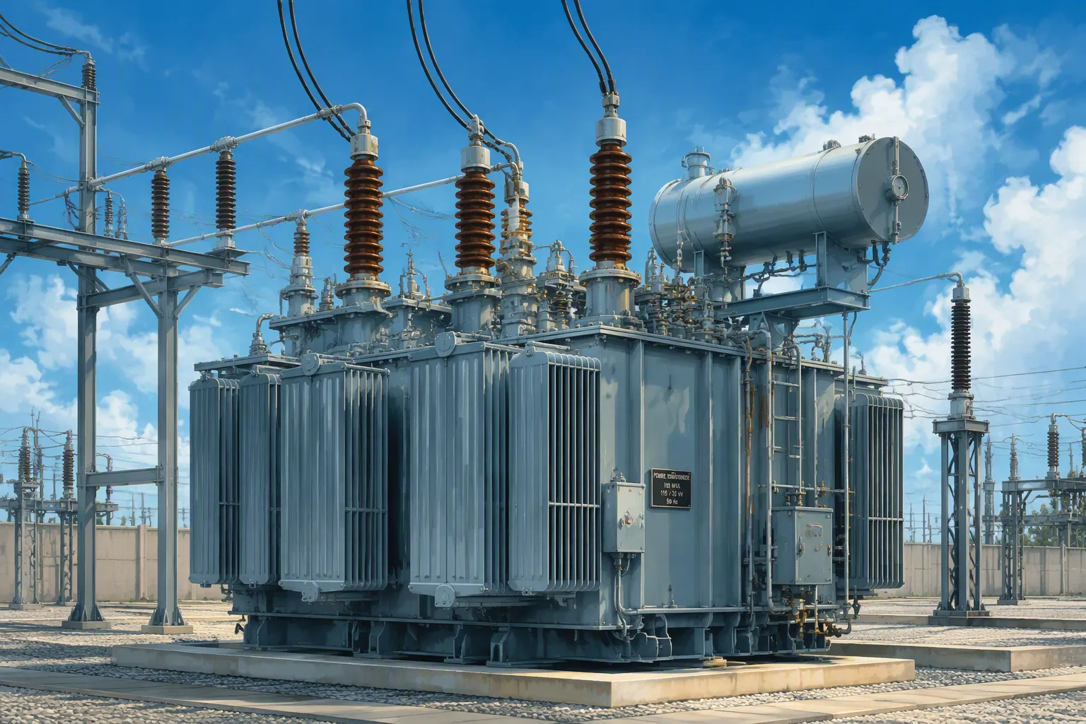
A power transformer is a static device that transfers electrical energy between circuits via electromagnetic induction. Its primary role is voltage regulation. You likely face a central question: How do you navigate the many transformer types to find the right fit for your project? Confusion often arises from choices like core versus shell type, oil versus dry cooling, or step-up versus step-down. This guide demystifies the types of transformers. It provides a practical framework for selection based on your application needs. You will gain concrete clarity on which electric transformer suits your specific scenario. Understanding the distinctions among transformers empowers informed decisions about these critical components.
Understand the main transformer types: step-up, step-down, isolation, and autotransformers.
Choose between single-phase and three-phase designs based on your power needs.
Select the right cooling method: dry-type for indoor safety, oil-immersed for outdoor high voltage.
Use instrument transformers (CTs and PTs) for safe measurement and protection.
Match voltage, capacity, and load characteristics to pick the perfect transformer.
Function determines how a power transformer serves your system. Each design performs a specific role in the electrical network, from generation through transmission to final consumption. Understanding these functional categories helps you match the right equipment to your operational requirements.
Step-up transformers operate at power generation facilities. They receive electricity from generators at relatively modest voltages and increase that voltage for efficient long-distance travel. This voltage elevation serves a critical purpose: higher voltages reduce current for the same power transfer, which minimizes resistive losses across transmission lines.
The voltage increase ratio varies substantially across installations. Typical step-up transformer configurations range from input voltages of 6.3kV to 10.5kV stepped up to outputs of 35kV to 110kV, producing ratios between 3.3 and 17.5. Larger utility installations might use inputs of 10kV to 35kV with outputs reaching 110kV to 220kV, yielding ratios from 3.1 to 22. Some very large generation stations employ even higher ratios, approaching 69.5 when stepping from 11kV-25kV up to 115kV-765kV for ultra high-voltage transmission.
You will find these transformers at hydroelectric dams, thermal plants, wind farms, and solar installations. A generator step-up transformer must handle continuous full-load operation with minimal losses. Manufacturers like RISEN ELECTRIC design these units with robust insulation systems to withstand the thermal and electrical stresses of continuous duty. The selection of a step-up transformer directly influences your transmission efficiency and overall plant economics.
Step-down transformers perform the inverse function. They reduce high transmission voltages to levels suitable for industrial, commercial, and residential consumption. These units appear throughout the power distribution network at various points in the delivery chain.
Substation transformers represent the first stage of voltage reduction. They step down transmission voltages to intermediate levels for regional distribution. Distribution transformers then perform the final reduction, bringing voltage to safe utilization levels for end users. Urban and rural networks rely on these units to deliver electricity at usable voltages while managing load fluctuations across the day.
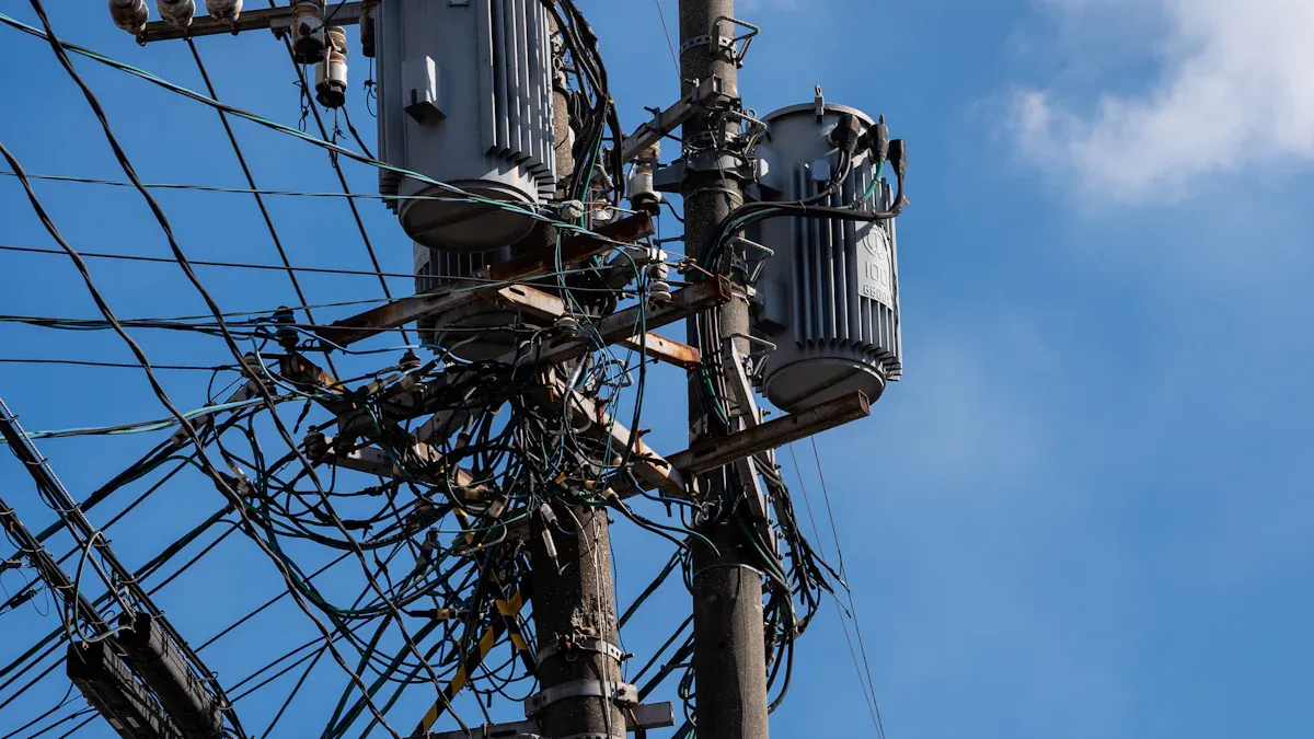
The types of power transformers in this category include pole-mounted units for residential neighborhoods, pad-mounted enclosures for commercial complexes, and vault installations for underground systems. Each configuration addresses specific space constraints and safety requirements. Distribution transformers often incorporate load management features that help utilities balance demand across their networks.
You should note that the types of power transformers extend beyond simple step-up and step-down functions. Isolation transformers provide electrical separation between circuits without changing voltage levels. These units protect sensitive equipment such as computers and medical devices from electrical noise and surges. They break the galvanic path between input and output, preventing ground loops and reducing electromagnetic interference.
The table below summarizes typical voltage transformation ranges for step-up applications:
|
Input Voltage (kV) |
Output Voltage (kV) |
Implied Voltage Ratio Range |
|---|---|---|
|
6.3 - 10.5 |
35 - 110 |
3.3 - 17.5 |
|
10 - 35 |
110 - 220 |
3.1 - 22 |
Your choice between step-up and step-down configurations depends entirely on your position within the electrical network. Generation facilities require step-up capability for high-voltage transmission. Distribution utilities and end users need step-down transformers for safe power delivery. Understanding these functional distinctions guides your equipment selection and ensures your system operates with optimal efficiency and reliability.
The number of phases fundamentally changes how a transformer delivers power. Your choice between single-phase and three-phase designs depends on the scale of your load and the nature of your application. Each configuration serves distinct segments of the electrical network.
Single-phase transformers deliver power through one alternating current waveform. They supply standard household voltage levels for lighting, appliances, and small motors. Utility companies deploy these units extensively in residential neighborhoods, typically mounting them on poles or placing them in pad-mounted enclosures.
Residential transformers commonly range from 25 kVA to 150 kVA. Standard sizes for single-family homes include 25 kVA, 50 kVA, and 75 kVA. Larger units at 100 kVA and 150 kVA serve apartment buildings or high-load residential complexes. A single-phase transformer suits applications where total demand remains modest and consistent.
You will find that single-phase designs cost less upfront than their three-phase counterparts. However, they exhibit higher no-load and load losses during operation. For small residential loads, this efficiency gap remains minor. The economic disadvantage becomes apparent only when you scale up demand significantly.
Three-phase transformers deliver power through three alternating current waveforms, offset by 120 degrees. This configuration provides smoother power flow and higher efficiency for the same total kVA. Industrial facilities, commercial complexes, and utility grids rely on three-phase transformer designs for heavy loads.
The minimum three-phase transformer size for industrial equipment typically starts at 112.5 kVA. Manufacturing plants, data centers, and large commercial buildings require this capacity to operate machinery, HVAC systems, and processing equipment. A three-phase transformer handles these demands with lower operating losses per kVA than comparable single-phase units.
The efficiency gap between configurations widens as load increases. For industrial and data center loads, this difference becomes significant. While a three-phase transformer carries a higher upfront cost than a single similar single-phase unit, it often proves cheaper per kVA than using three separate single-phase transformers of the same total rating. This cost advantage, combined with better efficiency and fewer parts, yields lower long-term maintenance and lifecycle costs.
The table below compares key economic aspects:
|
Aspect |
Single-Phase |
Three-Phase |
|---|---|---|
|
Initial Cost |
Lower |
Higher |
|
Long-term Losses |
Higher |
Lower |
|
Overall Efficiency |
Lower |
Higher |
|
Economic Outcome |
Less economical long-term |
More economical over time |
Your step-down transformer selection for power distribution must account for these phase considerations. A step-down transformer serving a residential subdivision will likely use single-phase construction. Industrial step-down applications demand three-phase designs for adequate capacity and efficiency.
The physical construction determines a unit's performance, cost, and application suitability. Two fundamental categories dominate the industry: core-type and shell-type designs. Each offers distinct advantages for different operating conditions.
Core-type units arrange windings around a laminated steel core. The core has two vertical limbs and two horizontal yokes forming a rectangular frame. Primary and secondary windings sit on separate limbs, with the low-voltage winding closer to the core and the high-voltage winding over it. This design exposes windings to ambient air, which improves cooling and contributes to better transformer efficiency. You find core-type units in high-voltage and high-power applications. Their simpler structure reduces manufacturing cost, making them ideal for cost-sensitive projects like rural electrification.
Shell-type units surround the windings with core material. The central limb carries total magnetic flux, while two outer limbs each carry half. Both windings occupy the central limb in layered arrangements. This construction provides higher mechanical strength and a more compact structure. However, enclosed windings reduce natural cooling effectiveness. Shell-type units serve low-to-medium power applications, including distribution and current transformers.
Core type transformers are characterized by low cost and excellent heat dissipation, whereas shell type transformers offer higher mechanical strength and a more compact structure, but at a higher cost.
Beyond core and shell configurations, specialized types of electrical transformers serve distinct functions. An autotransformer uses a single winding serving as both primary and secondary. This design reduces material usage and size. It provides lower impedance, which improves voltage regulation under load. You use an autotransformer for voltage regulation where galvanic isolation between circuits is unnecessary.
An isolation transformer provides complete electrical separation between input and output circuits. It uses two separate windings with no conductive path between them. The higher impedance can cause greater voltage drop under load, but this impedance helps limit fault current. You apply these units in medical equipment, electronic systems, and sensitive industrial controls.
These types of power transformers represent the primary construction categories. Understanding these types of electrical transformers helps you match design characteristics to your operational demands. Your knowledge of these types of transformers forms the foundation for selecting the right equipment. Among the types of electrical transformers, construction differences matter most for your specific application. These types of power transformers cover the main design variants you will encounter.
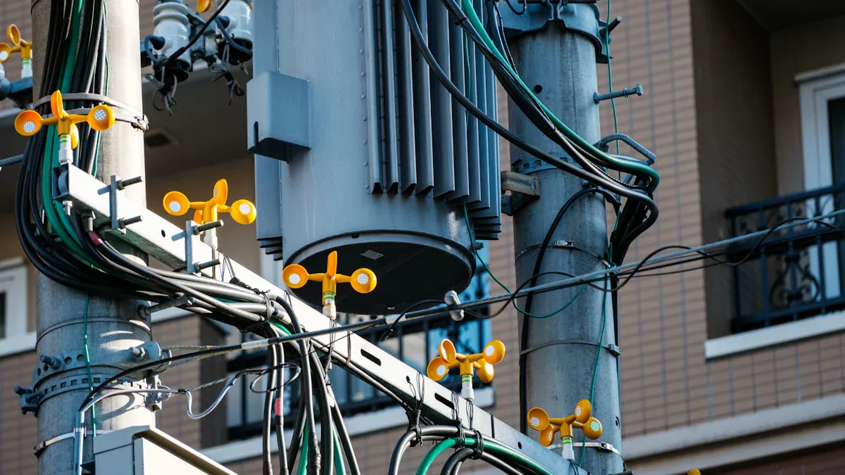
Cooling method determines where you can install a transformer and how it performs under load. Two primary cooling methods dominate the industry: dry-type and oil-immersed designs. Each serves distinct environments and operational requirements. Your choice between them directly impacts safety, maintenance, and overall system reliability.
A dry-type transformer uses air as the cooling medium. It eliminates the fire risk associated with oil-based cooling. This makes it ideal for indoor installations where fire safety is critical. You find these units in hospitals, hotels, high-rise buildings, and commercial complexes. Dry-type transformers comply with key safety standards including IEC 60076 for design and NFPA 70 for electrical safety.
The standard maximum ambient temperature for dry-type units is 40°C. With Class F insulation, the hot spot temperature limit reaches 155°C at 35°C ambient. The hot spot factor ranges from 1.1 to 1.2, lower than the 1.3 factor for oil-immersed designs. This means dry-type transformers can tolerate higher ambient temperatures before reaching their insulation limit. The table below shows the relationship between insulation class and temperature ratings:
|
Insulation Class |
Ambient Temp (°C) |
Rise (°C) |
Hot-Spot Temp (°C) |
|---|---|---|---|
|
Class A |
40 |
55 |
95 |
|
Class B |
40 |
65 |
105 |
|
Class F |
40 |
80 |
120 |
|
Class H |
40 |
100 |
140 |
Dry-type units come in three sub-types. Cast resin units carry the F1 fire behavior rating and are self-extinguishing. They offer excellent moisture resistance and suit humid locations such as hotels and hospitals. VPI units provide good fire performance with low smoke generation. They work well in offices and standard electrical rooms. Open ventilated units offer the lowest cost but require clean, climate-controlled environments. These designs maintain good transformer efficiency in indoor conditions.
An oil-immersed transformer uses mineral oil or synthetic fluids for cooling and insulation. The oil absorbs heat from the core and windings and transfers it to the tank surface. This provides superior heat dissipation for high voltage outdoor applications.
You use oil-immersed units in substations and utility installations where high-voltage transmission requires robust cooling. The oil serves double duty as both coolant and electrical insulator. This combination allows these units to handle higher power densities than dry-type designs of similar size. The hot spot factor for oil-immersed designs is 1.3, higher than the 1.1 to 1.2 range for dry-type units. This means internal temperature rise amplifies more in oil-immersed transformers, and you must account for this factor when sizing the equipment for your load conditions.
Both cooling methods offer high-efficiency designs suited to their operating environments. RISEN ELECTRIC manufactures a complete range of cooling solutions for both dry-type and oil-immersed transformers. Their product line includes cast resin units for indoor safety and oil-immersed units for outdoor installations.
Instrument transformers serve a specialized role in power systems. They scale down high currents and voltages to safe, measurable levels for relays, meters, and monitoring equipment. Without these devices, you cannot accurately measure or protect modern electrical networks. They bridge the gap between raw power and sensitive instrumentation.
A current transformer steps down high line currents to a standardized, low value for measurement. You connect the primary winding in series with the conductor carrying the load. The secondary winding then delivers a proportional current, typically 5A, to your metering equipment.
Metering CTs come with primary ratings from 50A up to 6000A. This range translates to transformation ratios from 50/5A (10:1) to 6000/5A (1200:1). Distribution applications commonly use lower ratios. Standard configurations include 50/5A, 75/5A, 100/5A, 150/5A, 200/5A, and 300/5A. Each ratio serves a specific load range. A 100/5A CT, for instance, accurately measures primary currents from about 70A to 90A.
Protection CTs differ from metering units in accuracy requirements. Grid protection relays demand precise performance under fault conditions. The accuracy class defines the composite error and saturation behavior. The table below summarizes common protection classes:
|
Accuracy Class |
Maximum Error |
Typical Application |
|---|---|---|
|
5P10 |
5% composite error, ALF = 10 |
Feeder Protection |
|
5P20 |
5% composite error, ALF = 20 |
Transformer Protection |
|
10P20 |
10% composite error, ALF = 20 |
Generator Protection |
The Accuracy Limit Factor (ALF) indicates the multiple of rated current a CT can reproduce before saturation. A 5P10 CT with a 100/5A rating maintains accuracy up to approximately 1000A. You select the class based on your protection scheme. Feeder protection typically uses 5P10, transformer protection uses 5P20, and generator protection uses 10P20.
A potential transformer steps down high voltage to a safe, standardized level for monitoring equipment. You connect the primary winding across the line. The secondary delivers a reduced voltage to your relays, meters, and protective devices.
Common PT secondary voltages include 100V, 120V, and 69.3V. Industrial metering often uses 100V, such as a 10kV/100V PT. Protection and metering applications commonly use 120V. The 69.3V secondary serves specific protection requirements.
Common PT secondaries include 120V and 69.3V, depending on protection and metering requirements.
A step-down transformer converts voltages such as 480V to 120VAC for monitoring equipment. This confirms 120V as a standard secondary voltage. You select the PT ratio based on your primary system voltage and the requirements of your connected devices. These transformers ensure your monitoring equipment operates safely while providing accurate voltage readings for system control.
Selecting the right equipment demands a systematic evaluation of your electrical system's requirements. You must examine voltage levels, capacity demands, load characteristics, and installation constraints. Each factor influences the final specification. A structured approach prevents costly missteps and ensures reliable long-term operation.
Your first step involves matching voltage ratings to your source and load requirements. The primary voltage must align with your incoming supply. The secondary voltage must match your utilization equipment. You also need to consider the basic insulation level (BIL) and whether you require tap changer capability for voltage adjustment. Incorrect voltage ratings lead to overheating or insulation failure.
Voltage regulation matters equally. A lower regulation percentage, typically 0.5% to 2% for power transformers, indicates better output stability under varying loads. Sensitive electronic equipment demands tighter regulation for consistent performance.
The table below summarizes the essential selection criteria:
|
Selection Criterion |
Key Considerations |
|---|---|
|
Voltage Rating |
Must match primary (source) and secondary (load) system voltages; includes insulation level (BIL) and tap changer range. Incorrect ratings cause overheating or insulation failure. |
|
Voltage Regulation |
Lower percentage (0.5%–2% for power transformers) indicates better stability; essential for sensitive loads and power quality. |
|
Capacity (kVA/MVA) |
Must cover continuous, peak, and future loads (20–30% margin). Optimal efficiency at 40–70% load; undersizing causes overheating, oversizing reduces efficiency. |
|
Load Characteristics |
Motor loads need 6–8× starting current capability; non-linear loads (VFDs, EV chargers) require K-factor or derating; renewable loads need reverse power flow and harmonic tolerance. |
|
Cooling & Standards |
Cooling class (ONAN/ONAF) affects overload capability; sizing follows IEC 60076-7 or IEEE C57.91 for thermal limits. |
Calculating your required transformer capacity follows a clear procedure:
Determine the total connected load (in kW) of all equipment.
Apply the demand factor to obtain the maximum expected demand: maximum demand = connected load × demand factor.
Calculate the required apparent power using the power factor: kVA = kW / power factor.
Consider the diversity factor to account for differing peak times of equipment, allowing more accurate sizing.
Add a reserve margin (e.g., 10–20%) for future expansion and safety.
For example, a facility with 800 kW maximum demand and a power factor of 0.8 requires 1000 kVA (800 / 0.8 = 1000). This calculation forms the foundation of your power transformer selection process.
Your installation site dictates the cooling method. Indoor locations demand dry-type transformers for fire safety. Outdoor substations can accommodate oil-immersed designs with superior heat dissipation. You must also consider ambient temperature, humidity, and altitude. These environmental conditions affect derating and insulation performance.
Regulatory compliance shapes your specification. International standards govern every aspect of transformer design and testing. The table below outlines the key standards:
|
Standard |
Description |
Scope |
|---|---|---|
|
IEC 60076-1 |
General requirements |
Covers design, construction, and testing fundamentals for all power transformers. |
|
IEC 60076-2 |
Temperature rise and cooling |
Defines thermal limits and cooling methods. |
|
IEC 60076-3 |
Insulation levels and dielectric tests |
Specifies insulation coordination and test procedures. |
|
IEC 60076-5 |
Short-circuit withstand |
Tests ability to withstand short-circuit forces. |
|
IEC 60076-7 |
Loading guide for oil-immersed transformers |
Provides safe loading practices. |
|
IEC 60076-10 |
Determination of sound levels |
Sets noise measurement standards. |
|
IEC 60076-14 |
Design for ester fluid transformers |
Specific requirements for liquid-immersed transformers using biodegradable fluids. |
|
IEC 60076-18 |
Frequency response analysis (FRA) |
Measurement of winding deformation. |
|
IEEE C57 series |
Power transformer performance and testing |
North American equivalent covering design, test codes, and application guidelines. |
These standards directly guide the selection of power transformers by defining performance, safety, and testing criteria that ensure international compatibility.
Energy efficiency regulations also affect your choice. The European standards, specifically EN 50588-1 and EU Regulation 548/2014 (as updated by Regulation 2021/340), impose strict limits on both load and no-load losses for power transformers. In the European Union, replacing outdated transformers with Tier 2-compliant models is now a legal obligation for distribution operators. This mandatory shift has resulted in significant reductions in technical losses, CO₂ emissions, and maintenance costs across the EU grid. The EU Ecodesign Regulation establishes two compliance tiers, with Tier 2 becoming mandatory from July 2021. Tier 2 significantly tightens efficiency requirements for both liquid-immersed and dry-type transformers compared to earlier standards.
Your final specification balances technical performance, operational environment, and regulatory obligations. Consulting with experienced manufacturers like RISEN ELECTRIC ensures your electric transformer meets all applicable codes while delivering optimal transformer efficiency for your specific application.
You encounter transformer applications across industries daily, often without noticing them. Each sector demands specific configurations tailored to its operational realities. Understanding these common transformer applications helps you recognize equipment requirements in your own facility.
Utility grids rely on transformers at every stage of power distribution. Step-up transformers at generation plants raise voltage for transmission. Step-down transformers at substations reduce voltage for safe consumer delivery. These applications across industries form the backbone of modern electrification.
Renewable energy installations present unique transformer applications across industries. Solar farms use step-up transformers to increase inverter output voltage for grid transmission. Wind farms employ similar units to raise collector system voltage for efficient long-distance power transfer. Hydropower plants boost generator voltage to transmission levels with dedicated transformers.
Wind turbine installations demonstrate specialized transformer design. Pad-mounted transformers sit at the turbine base for compact, outdoor-ready service. Nacelle transformers operate inside the housing, requiring vibration resistance and space efficiency. Collector system transformers at substations provide high reliability for long-distance collection. RISEN ELECTRIC manufactures units for each demanding position.
Industrial facilities depend on robust power distribution equipment. A distribution transformer delivers reliable voltage to production lines, HVAC systems, and processing equipment. Commercial complexes use step-down transformers to convert utility voltages to safe levels for lighting and office equipment.
Healthcare facilities demand exceptional electrical safety. An isolation transformer provides galvanic separation between hospital supply and sensitive medical equipment. This configuration shields devices from power surges, prevents earthing failures, and reduces electromagnetic noise through Faraday shields. Clean power enhances reliability of life-support and diagnostic systems.
A medical isolated-power system includes more than a transformer. Its design may require an ungrounded secondary, controlled leakage and capacitance, continuous insulation monitoring, appropriate distribution equipment, alarms, and application-specific testing. The purpose of this arrangement is not to declare the circuit shock-proof. It is to control ground-fault behaviour and continuously indicate deterioration of the system's isolation so that service continuity and electrical safety can be managed in the way required for the medical location.
Modern grids increasingly deploy smart transformer units with monitoring features. These devices report operational data in real time, enabling predictive maintenance and improved reliability. You will find them in urban substations and renewable installations alike.
You now have a clear mental checklist. Classify by function (step-up or step-down), phases, construction, cooling method, and application. Each category narrows your options toward the right power transformer.
Your choice of transformers balances technical specifications, operational environment, and cost. Voltage ratings, capacity, load characteristics, and site conditions all matter. Use these selection criteria as your starting point. Consult engineers or manufacturers for final specification and sizing.
Transformer technology continues evolving. Smart transformers with real-time monitoring and advanced materials improve grid reliability. Your foundational knowledge positions you to make informed decisions as these innovations arrive.
A step-up transformer increases voltage at generation sites. A step-down transformer reduces voltage at substations. Your choice between step-up and step-down configurations depends on your position in the electrical network.
Determine your total connected load in kW. Apply the demand factor. Divide by the power factor. Add a 10–20% reserve margin for future expansion. This calculation ensures your transformer handles peak demand without overheating.
Dry-type transformers suit indoor environments where fire safety matters. Outdoor installations typically require oil-immersed designs for superior heat dissipation and weather protection. Always consult local codes before specifying an installation location.
A well-maintained power transformer operates reliably for 20 to 30 years. Factors such as load conditions, ambient temperature, maintenance frequency, and insulation quality directly affect longevity. Regular testing extends service life.